background image

HARDWARE

Page 8 of 13

4 COMMISSIONING

1. Remove the air inlet cap, then screw the nozzle into hole:

1/4" NPT Male Quick-Release

Coupling

2. Put a few drops of lubricating oil (without resin acid) in the air inlet nozzle.
3. Check the flexible air supply hose.

If it is damaged, broken, torn or deformed it must not be connected to the tool.

4. Check the state of the quick-release couplings (both on the tool and the hose). If signs of

damage are detected, it is broken or excessively corroded, the tool or the flexible hose

cannot be used.

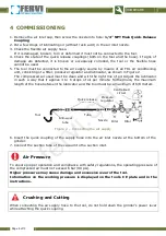
5. The tool must be connected to the air supply source by means of an FRL air conditioning

unit, consisting of a filter, pressure regulator and lubricator, as shown in Figure 2.
The compressed air used must be clean and with the right mix of oil. Adjust the lubricator

in such a way that it applies 3 to 6 drops of oil per minute. Furthermore, the maximum
length of the hose between the lubricator and the tool must be a maximum of 6/8 meters.

Figure 2 – Connecting the air supply

6. Insert the quick coupling of the supply hose into the air inlet nozzle at the bottom of the

grinder.

7. Connect the suction tube of the vacuum to the suction inlet.

Air Pressure

To ensure proper operation and compliance with safety regulations, the operating pressure of
the compressed air must not exceed 6 bar (90 psi).

Higher pressures may cause damage and excessive wear of the tool.
Information on the working pressure is displayed on the tool's CE plate and in the

instructions.

Crushing and Cutting

When connecting the air supply hose to the tool, do not hold down the grinder's power lever

while attaching the quick coupling.

Anti-wear

tube

Tool

Tube

Quick release

connector

Nozzle

Pressure

regulator

Filter

Oiler

Centralised

circuit

fervi.com

Содержание 419

Страница 1: ...OPERATION AND MAINTENANCE MANUAL 150 mm Air orbit sander Art 0419 ORIGINAL INSTRUCTIONS f e r v i c o m ...

Страница 2: ...of the necessary information and instruction and should be provided with adequate training regarding safety in pertaining to a The conditions of use of the device b Foreseeable abnormal situations pursuant to Article 73 of Legislative Decree 81 08 We guarantee the Machine s conformity to specifications and technical instructions described in the Manual on the date of issue listed on this page howe...

Страница 3: ...ving Parts 4 1 3 Personal protective equipment 5 1 4 Technical support 5 2 DESCRIPTION OF THE SANDER AND INTENDED USE 6 2 1 Technical specifications 6 3 IMPROPER USE AND CONTRAINDICATIONS 7 4 COMMISSIONING 8 5 HOW TO USE 9 5 1 Attaching the abrasive tools discs 9 5 2 Power On Off 9 6 MAINTENANCE AND CLEANING 11 7 BILL OF MATERIALS AND SPARE PARTS 12 f e r v i c o m ...

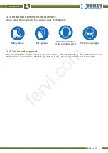
Страница 4: ...hting and visibility 3 Pay attention in unknown work environments and areas The pneumatic tool is not isolated from the power supply 4 Be especially careful to avoid contact with dust air jets or other pollutants If necessary wear a dust mask 5 It is important to maintain a stable and secure position while working Beware of air hoses which can cause you to trip and fall 1 2 Risks Associated with t...

Страница 5: ... following Safety shoes Work gloves Hearing protection cap earplugs etc Protective goggles 1 4 Technical support For any problems and or concerns please contact without hesitation the Customer Service Department of the dealer who has specialised staff specific equipment and spare parts f e r v i c o m ...

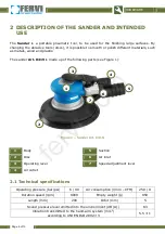
Страница 6: ... made up of the following parts see Figure 1 Figure 1 Sander Art 0419 1 Body 5 Suction 2 Disc 6 Air inlet 3 Operating lever 7 Speed adjustment lever 4 Air outlet 2 1 Technical specifications Operating pressure bar psi 6 90 Air consumption l min CFM 250 9 Rotation speed rpm 8000 Empty weight g 950 Length mm 200 Orbit mm 5 Sound pressure level emitted into the environment dB A 83 Vibration transmitt...

Страница 7: ...wearing appropriate PPE such as footwear gloves hearing protectors and goggles Touch rotating parts during operation Use the tool in the presence of children Leave the compressed air supply hose inserted after work or while changing the grinding wheel Point the sander in the direction of people or animals Block or insert objects into the air outlet grille Modify and or tamper with the tool Use pne...

Страница 8: ...the lubricator in such a way that it applies 3 to 6 drops of oil per minute Furthermore the maximum length of the hose between the lubricator and the tool must be a maximum of 6 8 meters Figure 2 Connecting the air supply 6 Insert the quick coupling of the supply hose into the air inlet nozzle at the bottom of the grinder 7 Connect the suction tube of the vacuum to the suction inlet Air Pressure T...

Страница 9: ...ective Equipment PPE Before using the sander wear suitable work clothing gloves shoes and protective goggles Also wear a mask if you work with materials that produce dust or fumes Also wear protective devices for the ears hearing protectors such as earmuffs earplugs etc Workspace Be familiar with the work area Always check the work area before using the sander Keep the work area clean uncluttered ...

Страница 10: ...n of the tool press down with the palm of your hand The sander s start lever is a continuous hold lever in the sense that the function controlled i e the rotation of the disc is active as long as the lever itself continues to be pressed Therefore release the lever to shut it down in an emergency Emergency In case of an emergency immediately release the sander s power lever Disconnect the air hose ...

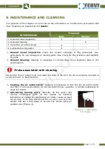
Страница 11: ...ody of oil deposits dust or dirt accumulation Risks associated with cleaning Disconnect the air supply hose and clean the body of the tool Do not use organic solvents to avoid corrosion or discolouration 3 Cleaning the air outlet nozzle cleaning is necessary to free the hot air outlet nozzle and filter of dirt accumulation Do not use paint thinner gasoline or similar substances to clean the nozzle...

Страница 12: ...HARDWARE Page 12 of 13 7 BILL OF MATERIALS AND SPARE PARTS f e r v i c o m ...

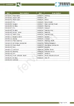
Страница 13: ...9 Knob valve 0419 31 Bearing 0419 10 Valve ring 0419 32 Sealing ring 0419 11 Bypass valve 0419 33 Gasket 0419 12 Spring 0419 34 C Ring 0419 13 Plain bearing 0419 35 Balance shaft 0419 14 Air intake connector 0419 36 Suction adaptor 0419 15 Main shaft 0419 37 Discharge connector 0419 16 Key 0419 38 O Ring 0419 17 Lock nut 0419 39 Muffler knob 0419 18 Bearing 0419 40 Exhaust cover 0419 19 Pin 0419 4...

Отзывы: