background image

Page 15

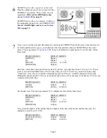
303 Automatic System Test

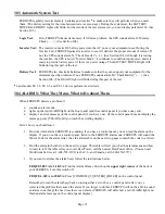
FERRUPS regularly tests its memory, batteries and inverter

 to make sure they will perform when you need

them. (The factory setting for the time between tests is seven days.) During the system test, the BATTERY
POWER and READY lights will blink. For the results of the last system test, you can display parameter 26. (See
Section 305.)

Logic Test:

First, FERRUPS checks its memory. If it finds a problem, the UPS sounds alarm O, Memory
Check (– – –). (See Section 304.)

Inverter Test: The inverter converts DC battery power into the AC power your equipment uses. During the

Inverter Test, FERRUPS pulses its inverter to see if it delivers the proper amount of current. If
not, the UPS sounds alarm N, “Check Inverter” (– 

). (See Section 304.) Although it is testing

the inverter, the UPS is not in “Inverter Mode”; it continues to condition input power, and it is
ready to provide battery power if there is a power outage. The BATTERY POWER light will
blink during this part of the test.

Battery Test: FERRUPS also checks its batteries to make sure that they can support your equipment for the

minimum specified runtime. If not, FERRUPS sounds alarm M, “Check Battery” (– –). (See
Section 304.) The READY light will blink during this part of the test.

Later models FE 1.8, FE 2.1, and FE 3.1 do not perform inverter tests.

304 ALARMS: What They Mean, What to Do about Them

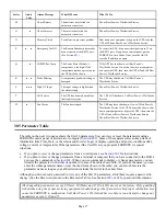
When FERRUPS detects a problem, it

 sounds an alarm code,

 lights up the red ALARM light on the front panel (and the control panel if you have one), and

 displays an error message on the control panel (if you have one). (If the control panel does not display the

message, press [CLEAR] until you reach the scrolling display.)

Here’s how you should react:

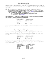
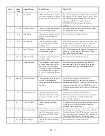
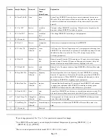
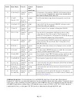
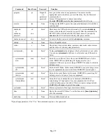
1. Find out which alarm FERRUPS is sounding. If you have a control panel, you can read the alarm on the

display. If you do not have a control panel, listen to the FERRUPS alarm code; FERRUPS will sound the
Morse Code for the alarm letter. (See the alarm table on the next two pages to match the code to a letter.)

2. Find the alarm in the table on the next two pages. This table will tell you what the alarm means and how

to react to it. If the table tells you to call Best Power, call the nearest Best Power office. (You can call
Worldwide Service at 1-608-565-2100; in the U.S. and Canada, call 1-800-356-5737.)

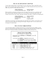
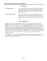
3. If you want to silence the alarm beep, follow the instructions below.

FE/QFE 500VA to 3.1KVA: Find the Alarm Silence Switch on the upper right corner of the back of
your FERRUPS. Turn this switch off.

FE/QFE 4.3kVA to 18KVA: Press [CONTROL] [5] [ENTER] [ENTER] on the control panel.

Remember to turn the alarm beep back on (using either a switch or a  control panel) after you’ve
corrected the problem that caused the alarm. If you forget to do this, FERRUPS will not be able to sound
an alarm code (beep) the next time there is an alarm. (FERRUPS will still show a red ALARM light and
flash an alarm message on the control panel display.)

Содержание FSS-0342J

Страница 1: ...FERRUPS Uninterruptible Power Systems FE or QFE 500VA to 18KVA 50 60 Hz USER MANUAL FSS 0342J Listed Models Available...

Страница 2: ...7200 Worldwide Service 1 800 356 5737 U S A Canada 1 608 565 2100 Service Fax 1 608 565 2509 International Fax 1 608 565 7675 International Service Fax 1 608 565 2799 Best Power Canada A Unit of Gener...

Страница 3: ...2 308 How and When to Shut Down Your FERRUPS 22 Section 400 Communication 24 401 Connecting a Terminal or Computer to the RS232 Port 25 402 Entering Commands from a Terminal or Computer 27 403 Remote...

Страница 4: ...er bulletin board service and CompuServe are available and Best Power has a World Wide Web site with more product information Best Power s toll free Fax on Demand service is also available 24 hours a...

Страница 5: ...ction for your model If your FERRUPS does not have a plug or if it has a separate battery cabinet make sure it has been installed before you go on If your FERRUPS looks like this drawing it is in the...

Страница 6: ...t 20 to 60 C 4 to 140 F Keep batteries in storage fully charged Recharge the batteries every 90 120 days Batteries will have a longer shelf life if you store them below 77 F 25 C 202 Startup FE and QF...

Страница 7: ...ould have a power cord that you can disconnect or unplug Disconnect this cord from your equipment and use it to plug in the UPS If you need to order a UPS power cord please call the nearest Best Power...

Страница 8: ...e CheckUPS II Suite monitors power conditions during a long power outage CheckUPS II automatically shuts down your computer system just before the FERRUPS runs out of battery power To install CheckUPS...

Страница 9: ...t be 0 95 without condensation The air must be free of dust chemicals that corrode or other contaminants and the air must be free to move around FERRUPS FERRUPS Features Front Panel Lights LEDs Contro...

Страница 10: ...ERRUPS has an input plug make sure the AC input power is off at the service panel Then plug in the UPS If the plug and your outlet receptacle do not match ask your electrician to install the outlet yo...

Страница 11: ...the service panel The green AC LINE light will light After a few seconds FERRUPS will switch from battery power inverter to AC input power The BATTERY POWER light should turn off If your FERRUPS does...

Страница 12: ...lay 0 Display 0 ENTER 00 Time 11 30 20 PROGRAM 00 Pgm Enter the correct time using the 24 hour system To do this you enter times from 1 00 a m to 12 59 p m just as you would read them from a clock Fro...

Страница 13: ...nstructions you received with the software That s it Your FERRUPS is now providing conditioned computer grade power to your equipment and FERRUPS is ready to provide power from its batteries if there...

Страница 14: ...and FE 3 1 the On Off switch is not on Not applicable READY Green FERRUPS is ready to provide backup power from its batteries when needed FERRUPS cannot provide backup power it may be in the Line Cond...

Страница 15: ...e may be times when you need to set the operating mode manually from the control panel Notice that the names of the operating modes appear in red on the bottom of keys 1 4 Operating Mode How to Select...

Страница 16: ...ide Service or the nearest Best Power office To enter the User Password follow these steps PRESS THIS KEY DISPLAY SHOWS CLEAR FERRUPS by BEST PROGRAM Password 3 7 7 Password 377 ENTER Level User When...

Страница 17: ...continue to show the UPS status and the control panel will show UPS alarms To enable the control panel again PRESS THESE KEYS DISPLAY READS CLEAR and ENTER together Unlock 8 2 0 4 9 Unlock 82049 ENTER...

Страница 18: ...RRUPS detects a problem it sounds an alarm code lights up the red ALARM light on the front panel and the control panel if you have one and displays an error message on the control panel if you have on...

Страница 19: ...de See your model s VA rating The unit will continue to run with overloads as high as 125 for 10 minutes and then shut down Reduce the amount of equipment using FERRUPS power and turn FERRUPS on again...

Страница 20: ...ment or bypass the UPS then turn the UPS off and call Best Power s Worldwide Service Phone Best Power s Worldwide Service 305 Parameter Table The table on the next two pages shows the first 26 paramet...

Страница 21: ...6 06 I Batt 0 0 Service ibatt ib Battery Current When the UPS is running on AC input this is the charging current in amps When the UPS runs on battery power inverter this is the amount of current in...

Страница 22: ...nit 21 21 OvrLds 0 Change Not Allowed overloads ol The number of times FERRUPS has sensed an overload that is the number of times VA Out has been greater than VA Limit 22 22 SysHrs 00000 Change Not Al...

Страница 23: ...ing and start it again 1 through 9 Go to the next log entry Each log entry consists of four pieces of information the alarm code the date month day of the alarm the time in 24 hour time and the durati...

Страница 24: ...both the Alarm and Inverter Logs These commands will display up to 20 log entries in a table For example the log might look like the table below Active EventDate EventTime Duration Code Event No 08 25...

Страница 25: ...Even when it s not powering your equipment FERRUPS will monitor its internal condition and keep the Time and Date parameters current There will be some times though when you want to shut down FERRUPS...

Страница 26: ...2 CAUTION Equipment will be damaged if you change the switch position when line is applied and the UPS is off or on inverter See TIP 410 2 Turn off FERRUPS On Off switch 3 If your FERRUPS is plugged...

Страница 27: ...can access through the RS232 port remote monitoring and remote shutdown The diagram below shows the functions of the pins at the FERRUPS communication port Pin Description 2 Transmit Data In 3 Receiv...

Страница 28: ...mputer you will need a cable designed specifically for this purpose See Figures 401 402 Best Power offers cables for computers or terminals using 25 pin or 9 pin serial ports call your local Best Powe...

Страница 29: ...s Specification Standard Setting Adjustable to Connector 25 pin D female wired as DCE Format ASCII 8 data bits 1 stop bit Most significant bit set to 0 Standard setting or 7 8 bits stop Baud Rate 1200...

Страница 30: ...test the alarm function Alarmtest sounds the User Test alarm J See Section 304 alarmtest cancel at c Turns the User Test alarm off chargermode chm None4 Shows the FERRUPS battery charger mode By enter...

Страница 31: ...re version inverterlog il None Displays the Inverter Log See Section 306 logs l None Displays both the Alarm and Inverter Logs See Section 306 message message m None Displays a message up to 16 charac...

Страница 32: ...ode alone displays which system mode is now active You can use systemmode with a o i or l to enter one of the modes below systemmode auto sm a None4 Enters the Auto Mode This is the normal FERRUPS mod...

Страница 33: ...a set of contacts that can apply FERRUPS 12 VDC on pin 6 to FERRUPS pin 21 You can use pin 18 instead of pin 6 do not use pin 14 Use a shielded single twisted pair cable to connect the switch to FERR...

Страница 34: ...nverter Your technician must observe important safety precautions while performing these checks For more information on what your technician should do in a Preventative Maintenance check or to schedul...

Страница 35: ...mps 3 3 amps 2 8 amps 6 2 amps 6 0 amps 5 7 amps 3 2 amps 3 1 amps 2 9 amps 7 0 amps 4 0 amps 3 4 amps 7 7 amps 7 2 amps 7 1 amps 3 8 amps 3 6 amps 3 5 amps 9 3 amps 5 7 amps 5 3 amps 5 0 amps 4 7 amp...

Страница 36: ...21 amps 100 68 amps 120 58 amps 200 34 amps 208 34 amps 220 31 amps 240 29 amps 220 31 amps 230 30 amps 240 28 amps 100 98 amps 120 82 amps 200 49 amps 208 48 amps 220 46 amps 240 41 amps 220 45 amps...

Страница 37: ...ine frequency up to limit which is adjustable from 0 01 Hz to 3 00 Hz Inverter turns on if line frequency exceeds the selected limit 604 Lightning and Surge Protection FERRUPS provides 2000 to 1 spike...

Страница 38: ...the low AC output shutdown setpoint the unit will alarm and shut down Some FERRUPS models have output receptacles protected by fuses or circuit breakers 608 Batteries and Battery Charger Standard batt...

Страница 39: ...unable to repair or replace the product to conform to this warranty after a reasonable number of attempts BEST POWER will refund the purchase price Remedies under this warranty are expressly limited...

Страница 40: ...hazards accident fire or other casualty misuse negligence incorrect wiring and any use or installation not in conformance with instructions furnished by BEST POWER or repairs or replacements needed b...

Страница 41: ...dem Extended Runtimes If you want extended runtimes call Best Power for information on adding additional battery capacity or an optional battery charger Interface Kits For computers that include their...

Страница 42: ...VA models IEC 320 receptacles are only available for QFE500VA QFE3 1KVA models QA QG EUROPEAN QB QF FRENCH IEC 320 SHUKO UNITED KINGDOM AUSTRALIAN SHUKO 10A 250V 10A 16A 250V 10A 250V 10A 250V 10 16A...

Страница 43: ...set out in the Radio Interference Regulations of the Canadian Department of Communications We hereby certify that the uninterruptible power system QFE 500VA 700VA 850VA 1 15KVA 1 4KVA 1 8KVA 2 1KVA 3...

Страница 44: ...r Off G Output Overload Q High PFM Temp H High Ambient Temp R Probe Missing I High Heatsink Temp S High AC Input J User Test Alarm T Call Service W Fan Alarm Best Power P O Box 280 Necedah Wisconsin 5...

Отзывы: