background image

ATLAS D 32 CONDENS K130 UNIT

26

ES

cod. 3541Q640  -  Rev. 00  -  10/2018
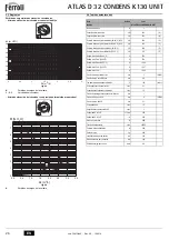
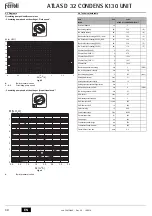
5.3 Diagramas
Pérdida de carga/altura de elevación circuladores
-  Altura de elevación del circulador con velocidad fija

fig. 45

A

Pérdidas de cargas de la caldera

1 - 2 - 3

Velocidad del circulador

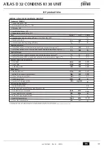
-  Altura de elevación del circulador con presión de impulsión proporcional

fig. 46

A

Pérdidas de cargas de la caldera

5.4 Tabla de datos técnicos

Min

.

4

1

7

III

II

I

0

1

2

3

4

5

6

7

0

0.5

1

1.5

2

 Q 

[m3/h]

2.5

3

8

[m H2O]

3

2

1

A

Min

.

4

1

7

III

II

I

0

1

2

3

4

5

6

7

H


[m H

2

O]

Q


[m

3

/h]

0.5

1.0

1.5

2.0

2.5

3.0

3.5

0.0

A

Dato

Unidad

Valor

Modelo

ATLAS D 32 CONDENS K130 UNIT

Número elementos

3

Capacidad térmica máxima

kW

33.0

(Q)

Capacidad térmica mínima

kW

16.3

(Q)

Potencia térmica máxima calefacción (80-60 °C) / ACS

kW

32.0

(P)

Potencia térmica mínima calefacción (80-60 °C) / ACS

kW

16.0

(P)

Potencia térmica máxima calefacción (50-30 °C)

kW

33.8

(P)

Potencia térmica mínima calefacción (50-30 °C)

kW

17.0

(P)

Rendimiento Pmáx. (80-60 °C)

%

97.2

Rendimiento Pmín. (80-60 °C)

%

97.8

Rendimiento Pmáx. (50-30 °C)

%

102.6

Rendimiento Pmín. (50-30 °C)

%

103.7

Rendimiento 30 %

%

103.6

Presión máxima en calefacción

bar

3

(PMS)

Presión mínima en calefacción

bar

0.8

Temperatura máxima agua calefacción

°C

100

(tmáx.)

Contenido circuito de calefacción

litros

21

Capacidad vaso expansión calefacción

litros

10

Presión de precarga vaso expansión calefacción

bar

1

Presión máxima en ACS

bar

9

(PMW)

Presión mínima en ACS

bar

0.1

Contenido de AS

litros

117

Capacidad vaso de expansión AS

litros

3

Caudal de AS 

t 30 °C

l/10 min

250

Caudal de AS 

t 30 °C

l/h

850

Grado de protección

IP

X0D

Tensión de alimentación

V/Hz

230/50

Potencia eléctrica absorbida

W

240

Peso sin carga

kg

245

Longitud cámara de combustión

mm

350

Diámetro cámara de combustión

mm

300

Pérdida de carga lado humos

mbar

0.11

Содержание ATLAS D 32 CONDENS K130 UNIT

Страница 1: ...ANUTENZIONE ES INSTRUCCIONES DE USO INSTALACIÓN Y MANTENIMIENTO EN INSTRUCTIONS FOR USE INSTALLATION AND MAINTENANCE FR INSTRUCTIONS D UTILISATION D INSTALLATION ET D ENTRETIEN EL ȅǻǾīǴǼȈ ȋȇdzȈǾȈ ǼīȀǹȉDZȈȉǹȈǾȈ Ȁǹǿ ȈȊȃȉdzȇǾȈǾȈ NL AANWIJZINGEN VOOR GEBRUIK INSTALLATIE EN ONDERHOUD cod 35414 40 Rev 0 10 201 4 ...

Страница 2: ... da un anodo di magnesio Il sistema di controllo è a microprocessore con interfaccia digitale con funzionalità avanzate di termo regolazione 2 2 Pannello comandi Pannello fig 1 Pannello di controllo Legenda pannello 1 Tasto decremento impostazione temperatura acqua calda sanitaria 2 Tasto incremento impostazione temperatura acqua calda sanitaria 3 Tasto decremento impostazione temperatura impianto...

Страница 3: ... ambiente con cronocomando remoto opzionale Impostare tramite il cronocomando remoto la temperatura ambiente desiderata all inter no dei locali La caldaia regolerà l acqua impianto in funzione della temperatura ambien te richiesta Per quanto riguarda il funzionamento con cronocomando remoto fare riferimento al relativo manuale d uso Temperatura scorrevole Quando viene installata la sonda esterna o...

Страница 4: ...ssere previsto lo spazio per lo smontaggio della mantellatura e per le normali attività di manutenzione 3 3 Collegamenti idraulici Avvertenze La potenzialità termica dell apparecchio va stabilita preliminarmente con un calcolo del fabbisogno di calore dell edificio secondo le norme vigenti L impianto deve essere cor redato di tutti i componenti per un corretto e regolare funzionamento Si consiglia...

Страница 5: ...lino decalcificatori in corrispondenza dell entrata dell ac qua fredda alla caldaia prestare particolare attenzione a non ridurre eccessi vamente il grado di durezza dell acqua in quanto potrebbe verificarsi un degrado prematuro dell anodo di magnesio del bollitore Sistema antigelo liquidi antigelo additivi ed inibitori La caldaia è equipaggiata di un sistema antigelo che attiva la caldaia in modo...

Страница 6: ... parte posteriore della caldaia rif A fig 26 al dispositivo di neutralizzazione alla rete delle acque reflue Le tubazioni di eva cuazione condensa devono essere resistenti agli acidi ed essere installate con almeno 3 di pendenza verso lo scarico evitando restrizioni ed occlusioni B IMPORTANTE Prima della messa in funzione dell apparecchio riempire il si fone d acqua ATTENZIONE l apparecchio non de...

Страница 7: ... accendere la caldaia Aprire le eventuali valvole di intercettazione tra caldaia ed impianti Verificare la tenuta dell impianto combustibile Verificare la corretta precarica del vaso di espansione Riempire l impianto idraulico ed assicurare un completo sfiato dell aria contenuta nella caldaia e nell impianto aprendo la valvola di sfiato aria posta nella caldaia e le eventuali valvole di sfiato sul...

Страница 8: ...uali occlusioni o ammaccature nei tubi di alimen tazione e ritorno del combustibile Effettuare la pulizia del filtro di linea di aspirazione del combustibile Rilevare il corretto consumo di combustibile Effettuare la pulizia della testa di combustione nella zona di uscita del combustibile sul disco di turbolenza Lasciare funzionare il bruciatore a pieno regime per circa dieci minuti quindi effet t...

Страница 9: ...a disinnesco Elettrodi d accensione mal regolati o sporchi Regolarli o pulirli Ugello otturato sporco o deformato Sostituire Regolazioni testa e serranda non adatte Regolare Elettrodi difettosi o a massa Sostituire Trasformatore d accensione difettoso Sostituire Cavi elettrodi difettosi o a massa Sostituire Cavi elettrodi deformati da alta temperatura Sostituire e proteggere Collegamenti elettrici...

Страница 10: ...Verificare la valvola di sicurezza Verificare il vaso di espansione A41 Posizionamento sensori Sensore mandata non inserito nel corpo caldaia Controllare il corretto posizionamento e funzionamento del sensore di riscaldamento F42 Anomalia sensore riscaldamento Sensore danneggiato Sostituire il sensore F47 Anomalia sensore di pressione acqua impianto Cablaggio interrotto Verificare il cablaggio Spe...

Страница 11: ...e Bollitore 154 Tubo scarico condensa 178 Bulbo termometro bollitore 179 Valvola di non ritorno 180 Bollitore 192 Ricircolo Ø 3 4 193 Sifone 197 Sfiato aria manuale 209 Mandata bollitore Ø 3 4 210 Ritorno bollitore Ø 3 4 233 Rubinetto scarico bollitore 246 Trasduttore di pressione 275 Rubinetto di scarico impianto di riscaldamento 278 Sensore doppio Riscaldamento Sicurezza 293 Flangia di ispezione...

Страница 12: ...tenza termica max riscaldamento 50 30 C kW 33 8 P Potenza termica min riscaldamento 50 30 C kW 17 0 P Rendimento Pmax 80 60 C 97 2 Rendimento Pmin 80 60 C 97 8 Rendimento Pmax 50 30 C 102 6 Rendimento Pmin 50 30 C 103 7 Rendimento 30 103 6 Pressione max esercizio riscaldamento bar 3 PMS Pressione min esercizio riscaldamento bar 0 8 Temperatura max riscaldamento C 100 tmax Contenuto acqua riscaldam...

Страница 13: ...ŝĐŽ ĚĞů ďƌƵĐŝĂƚŽƌĞ Ěŝ ĂĐĐĞŶƐŝŽŶĞ ŽŶƐƵŵŽ ĞŶĞƌŐĞƚŝĐŽ ĂŶŶƵŽ ŝǀĞůůŽ ĚĞůůĂ ƉŽƚĞŶnjĂ ƐŽŶŽƌĂ Ăůů ŝŶƚĞƌŶŽ ŵŝƐƐŝŽŶŝ Ěŝ ŽƐƐŝĚŝ Ěŝ ĂnjŽƚŽ WƌŽĨŝůŽ Ěŝ ĐĂƌŝĐŽ ĚŝĐŚŝĂƌĂƚŽ ůĂƐƐĞ Ěŝ ĞĨĨŝĐŝĞŶnjĂ ĞŶĞƌŐĞƚŝĐĂ Ěŝ ƌŝƐĐĂůĚĂŵĞŶƚŽ ĚĞůů ĂĐƋƵĂ ĚĂ Ă Ϳ ŽŶƐƵŵŽ ŐŝŽƌŶĂůŝĞƌŽ Ěŝ ĞŶĞƌŐŝĂ ĞůĞƚƚƌŝĐĂ ŽŶƐƵŵŽ ĂŶŶƵŽ Ěŝ ĞŶĞƌŐŝĂ ĞůĞƚƚƌŝĐĂ ĨĨŝĐŝĞŶnjĂ ĞŶĞƌŐĞƚŝĐĂ Ěŝ ƌŝƐĐĂůĚĂŵĞŶƚŽ ĚĞůů ĂĐƋƵĂ ŽŶƐƵŵŽ ŐŝŽƌŶĂůŝĞƌŽ Ěŝ ĐŽŵďƵƐƚŝďŝůĞ ŽŶƐƵŵŽ ĂŶŶƵŽ Ěŝ ĐŽŵďƵƐ...

Страница 14: ...Circolatore bollitore 138 Sonda esterna opzionale 139 Cronocomando Remoto opzionale 246 Trasduttore di pressione 278 Sensore doppio Sicurezza riscaldamento TR Trasformatore d accensione PR Preriscaldatore FR Fotoresistenza MB Motore bruciatore VE Valvola elettromagnetica DBM06E T T 278 OUT 5V GND 246 DSP05 L N 4 5 6 7 8 9 10 11 12 13 14 15 16 17 18 L N 230V 50Hz 42 32 138 139 72 130 TR MB 1 M PR T...

Страница 15: ...ƐƐĂ ƐĐůƵƐŝŽŶŝ ŽŶŽ ĞƐĐůƵƐŝ ĚĂůůĂ ƉƌĞƐĞŶƚĞ ŐĂƌĂŶnjŝĂ ŝ ĚŝĨĞƫ Ěŝ ĐŽŶĨŽƌŵŝƚă ĐĂƵƐĂƟ ĚĂ ͻ ƚƌĂƐƉŽƌƚŽ ŶŽŶ ĞīĞƩƵĂƚŽ Ă ĐƵƌĂ ĚĞůů ĂnjŝĞŶĚĂ ƉƌŽĚƵƩƌŝĐĞ ͻ ĂŶŽƌŵĂůŝƚă Ž ĂŶŽŵĂůŝĞ Ěŝ ƋƵĂůƐŝĂƐŝ ŐĞŶĞƌĞ ŶĞůů ĂůŝŵĞŶƚĂnjŝŽŶĞ ĚĞŐůŝ ŝŵƉŝĂŶƟ ŝĚƌĂƵůŝĐŝ ĞůĞƩƌŝĐŝ Ěŝ ĞƌŽŐĂnjŝŽŶĞ ĚĞů ĐŽŵďƵƐƟďŝůĞ Ěŝ ĐĂŵŝŶŝ Ğ Ž ƐĐĂƌŝĐŚŝ ͻ ĐĂůĐĂƌĞ ŝŶĂĚĞŐƵĂƟ ƚƌĂƩĂŵĞŶƟ ĚĞůů ĂĐƋƵĂ Ğ Ž ƚƌĂƩĂŵĞŶƟ ĚŝƐŝŶĐƌŽƐƚĂŶƟ ĞƌƌŽŶĞĂŵĞŶƚĞ ĞīĞƩƵĂƟ ͻ ĐŽƌƌŽƐŝŽŶŝ ĐĂƵƐĂƚĞ ĚĂ...

Страница 16: ...el panel 1 Tecla para disminuir la temperatura del ACS 2 Tecla para aumentar la temperatura del ACS 3 Tecla para disminuir la temperatura de calefacción 4 Tecla para aumentar la temperatura de calefacción 5 Pantalla 6 Tecla de selección del modo Verano Invierno 7 Tecla de selección del modo Economy Comfort 8 Tecla de rearme reset 9 Tecla para encender apagar el aparato 10 Tecla menú Temperatura ad...

Страница 17: ...egulación de la temperatura ambiente con el reloj programador a distancia opcional Mediante el reloj programador a distancia establecer la temperatura ambiente deseada en el interior de la vivienda La caldera regula el agua de la calefacción en función de la temperatura ambiente requerida Por lo que se refiere al funcionamiento con el reloj pro gramador a distancia consultar su manual de uso Tempe...

Страница 18: ...es normales de mantenimiento 3 3 Conexiones hidráulicas Advertencias La potencia térmica del aparato se debe calcular antes de instalarlo teniendo en cuenta las necesidades de calor del edificio según las normas vigentes Para el buen funciona miento del aparato la instalación hidráulica tiene que estar dotada de todos los compo nentes necesarios Se aconseja instalar válvulas de corte entre la cald...

Страница 19: ...a B No reducir excesivamente la dureza del agua cuando se instalan descalcifica dores en la entrada de agua fría a la caldera ya que ello puede causar la de gradación prematura del ánodo de magnesio del hervidor Sistema antihielo líquidos anticongelantes aditivos e inhibidores La caldera posee un sistema antiheladas que activa la calefacción cuando la tempera tura del agua de la instalación dismin...

Страница 20: ... al dispositivo de neutralización previo al desagüe final Los tubos de descar ga de condensados deben ser resistentes a los ácidos e instalarse con al menos 3 de pendiente hacia el desagüe evitando estrechamientos y oclusiones B IMPORTANTE Antes de poner el aparato en marcha llene el sifón de agua ATENCIÓN el aparato no debe funcionar nunca con el sifón vacío Verifique periódicamente que haya agua...

Страница 21: ... caldera Antes de encender la caldera Abrir las válvulas de corte si las hay entre la caldera y las instalaciones Verificar la estanqueidad del sistema del combustible Controlar la correcta precarga del vaso de expansión Llenar la instalación hidráulica y comprobar que no haya aire ni en la caldera ni en la instalación para ello abrir el purgador de aire de la caldera y los otros purgado res event...

Страница 22: ...cciones ni abolladuras en los tubos de entrada y retor no de combustible Limpiar el filtro de la tubería de entrada de combustible Comprobar que el consumo de combustible sea correcto Limpiar el cabezal de combustión en la zona de salida del combustible en el disco de turbulencia Dejar funcionar el quemador a pleno régimen alrededor de diez minutos y efectuar un análisis de la combustión verifican...

Страница 23: ...y compuerta Ajustar Electrodos averiados o a masa Cambiar Transformador de encendido averiado Cambiar Cables de los electrodos averiados o a masa Cambiar Cables de los electrodos deformados por alta temperatura Cambiar y proteger Conexiones eléctricas incorrectas de vál vula o transformador Controlar Acoplamiento motor bomba roto Cambiar Aspiración de la bomba conectada al tubo de retorno Corregir...

Страница 24: ...alación Controlar la válvula de seguridad Controlar el vaso de expansión A41 Posición de los senso res Sensor de ida no introducido en el cuerpo de la caldera Controlar la posición y el funciona miento del sensor de calefacción F42 Anomalía del sensor de calefacción Sensor averiado Cambiar el sensor F47 Anomalía del sensor de presión de agua de la instalación Cableado interrumpido Controlar el cab...

Страница 25: ...ostato regulación acumulador 154 Tubo descarga de condensados 178 Bulbo termómetro acumulador 179 Válvula antirretorno 180 Acumulador 192 Recirculación Ø 3 4 193 Sifón 197 Purgador de aire manual 209 Ida acumulador Ø 3 4 210 Retorno acumulador Ø 3 4 233 Llave de descarga del acumulador 246 Transductor de presión 275 Llave de descarga circuito calefacción 278 Sensor doble calefacción seguridad 293 ...

Страница 26: ... mínima calefacción 80 60 C ACS kW 16 0 P Potencia térmica máxima calefacción 50 30 C kW 33 8 P Potencia térmica mínima calefacción 50 30 C kW 17 0 P Rendimiento Pmáx 80 60 C 97 2 Rendimiento Pmín 80 60 C 97 8 Rendimiento Pmáx 50 30 C 102 6 Rendimiento Pmín 50 30 C 103 7 Rendimiento 30 103 6 Presión máxima en calefacción bar 3 PMS Presión mínima en calefacción bar 0 8 Temperatura máxima agua calef...

Страница 27: ...ĐŝĚĂĚ ĚĞů ƋƵĞŵĂĚŽƌ ĚĞ ĞŶĐĞŶĚŝĚŽ ŽŶƐƵŵŽ ĂŶƵĂů ĚĞ ĞŶĞƌպà EŝǀĞů ĚĞ ƉŽƚĞŶĐŝĂ ĂĐƷƐƚŝĐĂ ŵŝƐŝŽŶĞƐ ĚĞ ſdžŝĚŽƐ ĚĞ ŶŝƚƌſŐĞŶŽ WĞƌĨŝů ĚĞ ĐĂƌŐĂ ĚĞĐůĂƌĂĚŽ ůĂƐĞ ĞĨŝĐŝĞŶĐŝĂ ĞŶĞƌŐĠƚŝĐĂ ĚĞů ĐĂůĚĞŽ ĚĞ ĂŐƵĂ ĚĞ Ă Ϳ ŽŶƐƵŵŽ ĚŝĂƌŝŽ ĚĞ ĞůĞĐƚƌŝĐŝĚĂĚ ŽŶƐƵŵŽ ĂŶƵĂů ĚĞ ĞůĞĐƚƌŝĐŝĚĂĚ ĨŝĐŝĞŶĐŝĂ ĞŶĞƌŐĠƚŝĐĂ ĚĞů ĐĂůĚĞŽ ĚĞ ĂŐƵĂ ŽŶƐƵŵŽ ĚŝĂƌŝŽ ĚĞ ĐŽŵďƵƐƚŝďůĞ ŽŶƐƵŵŽ ĂŶƵĂů ĚĞ ĐŽŵďƵƐƚŝďůĞ DĂƌĐĂ ĐŽŵĞƌĐŝĂů ZZK ĂůĚĞƌĂ ĚĞ ĐŽŶĚĞŶƐĂĐŝſŶ 1 ĂůĚĞƌ...

Страница 28: ...Circulador del acumulador 138 Sonda exterior opcional 139 Cronomando a distancia opcional 246 Transductor de presión 278 Sensor doble seguridad calefacción TR Transformador de encendido PR Precalentador FR Fotorresistencia MB Motor quemador VE Válvula electromagnética DBM06E T T 278 OUT 5V GND 246 DSP05 L N 4 5 6 7 8 9 10 11 12 13 14 15 16 17 18 L N 230V 50Hz 42 32 138 139 72 130 TR MB 1 M PR Tm V...

Страница 29: ...S L U FÉRROLI ESPAÑA S L U durante el período de garantía durante el período de garantía Si el montaje no respeta las instrucciones que se suministran en la máquina Si el montaje no respeta las instrucciones que se suministran en la máquina La instalación de la máquina no respeta las Leyes y Reglamentaciones en vigor electricidad hidráulicas combustibles La instalación de la máquina no respeta las...

Страница 30: ...um anode The control system is with microprocessor and digital interface with advanced temperature control functions 2 2 Control panel Panel fig 1 Control panel Panel key 1 DHW temperature setting decrease button 2 DHW temperature setting increase button 3 Heating system temperature setting decrease button 4 Heating system temperature setting increase button 5 Display 6 Summer Winter mode selectio...

Страница 31: ...e Room temperature adjustment with optional remote timer control Using the remote timer control set the temperature desired in the rooms The boiler unit will set the system water according to the required room temperature For information on the remote timer control please refer to its user s manual Sliding temperature When the optional external probe is installed the control panel display detail 5...

Страница 32: ...d alongside a space must be pro vided for removing the casing and for normal maintenance operations 3 3 Plumbing connections Important The heating capacity of the unit must be previously established by calculating the build ing s heat requirement according to the current regulations The system must be provid ed with all the components for correct and regular operation It is advisable to install sh...

Страница 33: ...nishing water in the system B If water softeners are installed at the boiler cold water inlet make sure not to reduce the water hardness too much as this could cause early deterioration of the magnesium anode in the hot water tank Antifreeze system antifreeze fluids additives and inhibitors The boiler is equipped with an antifreeze system that turns on the boiler in heating mode when the system de...

Страница 34: ...cated on the back of the boiler ref A fig 26 to the waste water system neutralisation device The condensate discharge pipes must be acidproof and installed sloping at least 3 towards the drain without any constrictions and occlusions B IMPORTANT Fill the trap with water before starting the unit ATTENTION The unit must never be operated with the trap empty Periodically check the water in the trap f...

Страница 35: ...ety devices or parts of the boiler Before lighting the boiler Open any on off valves between the boiler and the systems Check the tightness of the fuel system Check the pre filling of the expansion tank Fill the water system and make sure that all air contained in the boiler and the sys tem has been vented by opening the air vent valve on the boiler and any vent valves on the system Make sure ther...

Страница 36: ... the fuel supply and return pipes Clean the fuel intake line filter Check correct fuel consumption Clean the combustion head in the fuel outlet zone on the turbulence disc Leave the burner operating at max for about ten minutes then analyse the combus tion checking Correct setting of all the elements specified in this manual Fume temperatures at the flue CO2 percentage content The ducts must be fr...

Страница 37: ...formed Replace Unsuitable head and shutter adjustments Adjust Faulty electrodes or earthed Replace Faulty ignition transformer Replace Faulty electrode wires or earthed Replace Electrode wires deformed by high temperature Replace and protect Faulty valve or transformer electrical connections Check Broken pump motor joint Replace Pump inlet connected to return pipe Correct the connection Faulty pho...

Страница 38: ...r not inserted in boiler shell Check the correct positioning and operation of the heating sensor F42 Heating sensor fault Sensor damaged Replace the sensor F47 Systemwaterpressure sensor fault Wiring disconnected Check the wiring Off Circulating pump on STANDBY Green ON Circulating pump Working Green Flashing Air venting cycle Green Red alternating Circulating pump blocked due to external causes O...

Страница 39: ...thermostat 154 Condensate drain pipe 178 Hot water tank thermometer bulb 179 Non return valve 180 Hot water tank 192 Recirculation Ø 3 4 193 Trap 197 Manual air vent 209 Hot water tank delivery Ø 3 4 210 Hot water tank return Ø 3 4 233 Hot water tank drain cock 246 Pressure transducer 275 Heating system drain cock 278 Double sensor Heating Safety 293 Hot water tank inspection flange 295 Burner 338...

Страница 40: ... heating 80 60 C DHW kW 16 0 P Max Heat Output in heating 50 30 C kW 33 8 P Min Heat Output in heating 50 30 C kW 17 0 P Efficiency Pmax 80 60 C 97 2 Efficiency Pmin 80 60 C 97 8 Efficiency Pmax 50 30 C 102 6 Efficiency Pmin 50 30 C 103 7 Efficiency 30 103 6 Max working pressure in heating bar 3 PMS Min working pressure in heating bar 0 8 Max heating temperature C 100 tmax Heating water content li...

Страница 41: ...ĞƌĂƚƵƌĞ ƌĞŐŝŵĞ ΎΎͿ ƚ ĨƵůů ůŽĂĚ ƚ ƉĂƌƚ ůŽĂĚ Ŷ ƐƚĂŶĚďLJ ŵŽĚĞ ƚĂŶĚďLJ ŚĞĂƚ ůŽƐƐ ŐŶŝƚŝŽŶ ďƵƌŶĞƌ ƉŽǁĞƌ ĐŽŶƐƵŵƉƚŝŽŶ ŶŶƵĂů ĞŶĞƌŐLJ ĐŽŶƐƵŵƉƚŝŽŶ ŽƵŶĚ ƉŽǁĞƌ ůĞǀĞů ŵŝƐƐŝŽŶƐ ŽĨ ŶŝƚƌŽŐĞŶ ŽdžŝĚĞƐ ĞĐůĂƌĞĚ ůŽĂĚ ƉƌŽĨŝůĞ tĂƚĞƌ ŚĞĂƚŝŶŐ ĞŶĞƌŐLJ ĞĨĨŝĐŝĞŶĐLJ ĐůĂƐƐ ĨƌŽŵ ƚŽ Ϳ ĂŝůLJ ĞůĞĐƚƌŝĐŝƚLJ ĐŽŶƐƵŵƉƚŝŽŶ ŶŶƵĂů ĞůĞĐƚƌŝĐŝƚLJ ĐŽŶƐƵŵƉƚŝŽŶ tĂƚĞƌ ŚĞĂƚŝŶŐ ĞŶĞƌŐLJ ĞĨĨŝĐŝĞŶĐLJ ĂŝůLJ ĨƵĞů ĐŽŶƐƵŵƉƚŝŽŶ ŶŶƵĂů ĨƵĞů ĐŽŶƐƵŵƉƚŝŽŶ dƌĂĚĞŵĂƌŬ ZZK ŽŶĚ...

Страница 42: ...130 Hot water tank circulating pump 138 External probe optional 139 Remote Timer Control optional 246 Pressure transducer 278 Double sensor Safety Heating TR Ignition transformer PR Preheater FR Photoresistance MB Burner motor VE Electromagnetic valve DBM06E T T 278 OUT 5V GND 246 DSP05 L N 4 5 6 7 8 9 10 11 12 13 14 15 16 17 18 L N 230V 50Hz 42 32 138 139 72 130 TR MB 1 M PR Tm VE FR ...

Страница 43: ...trôle fait appel à un microprocesseur muni d interface numérique et de fonctions avancées de régulation de la température 2 2 Tableau des commandes Panneau fig 1 Panneau de contrôle Légende panneau 1 Touche pour réduire la température de l eau chaude sanitaire 2 Touche pour augmenter la température de l eau chaude sanitaire 3 Touche pour diminuer la température de l installation de chauffage 4 Tou...

Страница 44: ...tion de la température ambiante par chronocommande à distance en option Programmer à l aide de la chronocommande à distance la température souhaitée à l in térieur des pièces La chaudière réglera la température dans le circuit d eau de l instal lation en fonction de la température ambiante demandée Pour le fonctionnement par chronocommande à distance se reporter au manuel d utilisation spécifique ...

Страница 45: ...rtissements La capacité thermique de l appareil sera préalablement définie à l aide d un calcul des besoins caloriques de l édifice conformément aux normes en vigueur L installation doit comprendre tous les accessoires requis pour garantir un fonctionnement correct et ré gulier Il est conseillé d installer entre la chaudière et le circuit des vannes d arrêt ou d isolement permettant au besoin d is...

Страница 46: ...trants au niveau de l entrée de l eau froide dans la chaudière faire particulièrement attention à ne pas réduire de façon excessive la dureté de l eau car cela entraînerait une dégradation prématurée de l anode de magnésium du ballon Système antigel produits antigel additifs et inhibiteurs La chaudière est équipée d un système antigel dans l électronique de fonctionnement qui active la chaudière e...

Страница 47: ...t à l arrière de la chaudière réf A fig 26 au dispositif de neutralisation sur le réseau des eaux usées Les conduits d évacuation de la condensation doivent pouvoir résister aux acides et avoir une inclinaison d au moins 3 vers l évacuation en évitant tout étranglement ou occlusion B IMPORTANT Avant de mettre l appareil en marche remplir le siphon d eau ATTENTION ne jamais mettre l appareil en mar...

Страница 48: ...ns sur des dispositifs de sécurité ou parties de la chaudière Avant d allumer la chaudière Ouvrir les soupapes d arrêt éventuelles entre la chaudière et l installation Vérifier l étanchéité du circuit de gazole Vérifier la précharge du vase d expansion Remplir les tuyauteries et assurer l évacuation complète de l air dans la chaudière et les installations en ouvrant la vanne d évent d air sur la c...

Страница 49: ...dommagées Nettoyer le filtre d aspiration du combustible Noter la consommation de combustible correcte Effectuer le nettoyage de la tête de combustion dans la zone de sortie du combustible sur le di sque de turbulence Faire fonctionner le brûleur à pleine allure pendant dix minutes et analyser la combustion en véri fiant les réglages corrects de tous les éléments indiqués dans la présente notice l...

Страница 50: ...es sales ligne pompe gicleur Nettoyer Pompe désarmorcée Amorcer et rechercher la cause du désarmorçage Électrodes d allumage mal réglées ou sales Régler ou nettoyer les électrodes Gicleur bouché sale ou déformé Remplacer Mauvais réglages de la tête et du registre d air Régler Électrodes défectueuses ou à la masse Remplacer Transformateur d allumage défectueux Remplacer Câbles électrodes défectueux...

Страница 51: ... installa tion incorrecte Pression trop haute Vérifier l installation Contrôler la soupape de sécurité Vérifier le vase d expansion A41 Positionnement des capteurs Capteur de départ non monté sur le corps de la chaudière Contrôler le positionnement et le fonctionnement corrects du capteur de température chauffage F42 Anomalie capteur de température chauffage Capteur endommagé Remplacer le capteur ...

Страница 52: ...143 Thermostat de réglage ballon 154 Tuyau d évacuation des condensats 178 Sonde thermomètre ballon 179 Clapet anti retour 180 Ballon 192 Recirculation Ø 3 4 193 Siphon 197 Évent air manuel 209 Départ ballon Ø 3 4 210 Retour ballon Ø 3 4 233 Robinet de vidange ballon 246 Transducteur de pression 275 Robinet de vidange circuit chauffage 278 Capteur double chauffage sécurité 293 Flasque d inspection...

Страница 53: ...0 C Sanitaire kW 16 0 P Puissance thermique maxi chauffage 50 30 C kW 33 8 P Puissance thermique mini chauffage 50 30 C kW 17 0 P Rendement Pmax 80 60 C 97 2 Rendement Pmin 80 60 C 97 8 Rendement Pmax 50 30 C 102 6 Rendement Pmin 50 30 C 103 7 Rendement 30 103 6 Pression maxi d utilisation chauffage bar 3 PMS Pression mini d utilisation chauffage bar 0 8 Température maxi chauffage C 100 tmax Capac...

Страница 54: ...ŽŵŵĂƚŝŽŶ ĂŶŶƵĞůůĞ Ě ĠŶĞƌŐŝĞ EŝǀĞĂƵ ĚĞ ƉƵŝƐƐĂŶĐĞ ĂĐŽƵƐƚŝƋƵĞ ŵŝƐƐŝŽŶƐ Ě ŽdžLJĚĞƐ Ě ĂnjŽƚĞ WƌŽĨŝů ĚĞ ƐŽƵƚŝƌĂŐĞ ĚĠĐůĂƌĠ ůĂƐƐĞ Ě ĞĨĨŝĐĂĐŝƚĠ ĠŶĞƌŐĠƚŝƋƵĞ ƉŽƵƌ ůĞ ĐŚĂƵĨĨĂŐĞ ĚĞ ů ĞĂƵ ĚĞ ă Ϳ ŽŶƐŽŵŵĂƚŝŽŶ ũŽƵƌŶĂůŝğƌĞ Ě ĠůĞĐƚƌŝĐŝƚĠ ŽŶƐŽŵŵĂƚŝŽŶ ĂŶŶƵĞůůĞ Ě ĠůĞĐƚƌŝĐŝƚĠ ĨĨŝĐĂĐŝƚĠ ĠŶĞƌŐĠƚŝƋƵĞ ƉŽƵƌ ůĞ ĐŚĂƵĨĨĂŐĞ ĚĞ ů ĞĂƵ ŽŶƐŽŵŵĂƚŝŽŶ ũŽƵƌŶĂůŝğƌĞ ĚĞ ĐŽŵďƵƐƚŝďůĞ ŽŶƐŽŵŵĂƚŝŽŶ ĂŶŶƵĞůůĞ ĚĞ ĐŽŵďƵƐƚŝďůĞ DĂƌƋƵĞ ĐŽŵŵĞƌĐŝĂůĞ ZZK ŚĂ...

Страница 55: ...tion 130 Circulateur ballon 138 Sonde extérieure option 139 Chronocommande à distance option 246 Transducteur de pression 278 Capteur double sécurité chauffage TR Transformateur d allumage PR Réchauffeur FR Cellule photorésistante MB Moteur brûleur VE Soupape électromagnétique DBM06E T T 278 OUT 5V GND 246 DSP05 L N 4 5 6 7 8 9 10 11 12 13 14 15 16 17 18 L N 230V 50Hz 42 32 138 139 72 130 TR MB 1 ...

Страница 56: ...l boiler voor warm sanitair water met magnesiumanode voor roestwering Het controlesysteem werkt met een microprocessor met digitale interface met geavanceerde functies voor warmteregeling 2 2 Bedieningspaneel Paneel fig 1 Controlepaneel Legenda paneel 1 Toets verlagen ingestelde temperatuur warm sanitair water 2 Toets verhogen ingestelde temperatuur warm sanitair water 3 Toets verlagen ingestelde ...

Страница 57: ...andsbediening Stel met behulp van de timerafstandsbediening de gewenste temperatuur voor de ver trekken in De verwarmingsketel stelt de temperatuur van het water in de installatie af op grond van de gewenste omgevingstemperatuur Voor wat de werking met timerafstand sbediening betreft wordt verwezen naar de betreffende gebruikershandleiding Weersafhankelijke temperatuur Wanneer de externe temperatu...

Страница 58: ...udswerkzaamheden te kunnen uitvoeren 3 3 Hydraulische aansluitingen Aanwijzingen Het thermisch vermogen van het apparaat moet vooraf worden vastgesteld door berekening van de warmtebehoefte van het gebouw volgens de geldende voorschriften De installatie moet uitge rust zijn met alle componenten zodat ze correct en regelmatig kan werken Het is raadzaam om tussen verwarmingsketel en verwarmingsinsta...

Страница 59: ...laat van het koude water van de verwar mingsketel wordt geïnstalleerd dient u erop te letten dat de hardheidsgraad niet te laag wordt daar de magnesiumanode van de boiler daardoor sneller achteruit kan gaan Antivriessysteem antivriesmiddel additieven en remmende stoffen De verwarmingsketel is uitgerust met een antivriessysteem dat de ketel inschakelt in ve rwarmingsmodus wanneer de temperatuur van...

Страница 60: ...ie Sluit de condensafvoerleiding op de achterkant van de verwarmingsketel detail A fig 26 aan op het condensneutralisatiesysteem en op het afvalwaternet De condensafvoerleidingen moeten zuurbesten dig zijn en minstens 3 naar de afvoer hellen zonder vernauwingen of verstoppingen B BELANGRIJK Alvorens het apparaat in werking te stellen de sifon met water vullen LET OP het apparaat mag nooit in werki...

Страница 61: ...Alvorens de verwarmingsketel te ontsteken Zet eventuele afsluitkleppen tussen verwarmingsketel en installaties open Controleer of het brandstofsysteem lekdicht is Controleer of het expansievat goed voorbelast is Vul de hydraulische installatie en zorg ervoor dat de verwarmingsketel en de instal latie volledig ontlucht zijn door de ontluchtingsklep op de verwarmingsketel en de eventuele ontluchting...

Страница 62: ...idingen niet verstopt of beschadigd zijn Reinig het filter van de brandstofaanzuigleiding Bepaal het juiste brandstofverbruik Reinig de verbrandingskop bij de brandstofuitgang op de wervelschijf Laat de brander gedurende ongeveer 10 minuten op volle kracht werken en analy seer daarna het verbrandingsproces als volgt De juiste afstelling van alle elementen die in deze handleiding vermeld staan Temp...

Страница 63: ...en oorzaak van uitschakelen opsporen Ontstekingselektroden slecht geregeld of vuil Afstellen of schoonmaken Sproeier verstopt vuil of vervormd Vervangen Regelingen kop en schuif niet geschikt Afstellen Elektroden defect of naar massa Vervangen Ontstekingstransformator defect Vervangen Elektrodekabels defect of naar massa Vervangen Elektrodekabels vervormd door hoge temperatuur Vervangen en afscher...

Страница 64: ...ontroleer de installatie Controleer de veiligheidsklep Controleer het expansievat A41 Plaats sensoren Sensor drukzijde niet aangebracht in ketelbehuizing Controleer positie en werking van de verwarmingssensor F42 Storing verwarmingssensor Sensor beschadigd Vervang de sensor F47 Storing sensor waterdruk installatie Breuk in bedrading Controleer de bedrading Uitgeschakeld Circulatiepomp in STAND BY ...

Страница 65: ... boiler 143 Regelthermostaat Boiler 154 Condensafvoerslang 178 Thermometerbol boiler 179 Terugslagklep 180 Boiler 192 Hercirculatie Ø 3 4 193 Sifon 197 Handbediende ontluchtingsklep 209 Toevoer boiler Ø 3 4 210 Retour boiler Ø 3 4 233 Afvoerkraan boiler 246 Drukomzetter 275 Aftapkraan verwarmingsinstallatie 278 Dubbele sensor Verwarming Veiligheid 293 Inspectieflens boiler 295 Brander 338 Rookrecu...

Страница 66: ... P Min warmtevermogen verwarming 80 60 C sanitair water kW 16 0 P Max warmtevermogen verwarming 50 30 C kW 33 8 P Min warmtevermogen verwarming 50 30 C kW 17 0 P Pmax rendement 80 60 C 97 2 Pmin rendement 80 60 C 97 8 Pmax rendement 50 30 C 102 6 Pmin rendement 50 30 C 103 7 Rendement 30 103 6 Max bedrijfsdruk verwarming bar 3 PMS Min bedrijfsdruk verwarming bar 0 8 Max verwarmingstemperatuur C 10...

Страница 67: ...tie 130 Circulatiepomp boiler 138 Externe sonde optie 139 Klokthermostaat met afstandsbediening optioneel 246 Drukomzetter 278 Dubbele sensor Beveiliging verwarming TR Ontstekingstransformator PR Voorverwarmer FR Fotoweerstand MB Brandermotor VE Magneetklep DBM06E T T 278 OUT 5V GND 246 DSP05 L N 4 5 6 7 8 9 10 11 12 13 14 15 16 17 18 L N 230V 50Hz 42 32 138 139 72 130 TR MB 1 M PR Tm VE FR ...

Страница 68: ...fort 8 ί ά 9 ί ί ί ή 10 ί ύ ή ί 11 Έ ί έ ί ύ ύ ή ή 12 ύ ύ ύ ή ή 13 Έ ί ύ ή ή 14 ύ ί ό ύ ύ ή ή 15 Έ ί Eco Economy ή Comfort 16 ί ύ ή ό ό ή 17 ί ό ί ό ή ή έ ά ί 18 ί ά ό έ ά 19 Έ έ ή 20 Έ ί ί ό ό 21 Έ ί ά έ 22 Έ ί 23 ύ ί ή έ 24 ύ έ 25 Έ ί έ 26 Έ ί έ ί ή έ 27 Έ ή ί ί ά ά ί έ ή έ έ ά ώ ή έ ά ύ ό ύ ύ έ ή ά ό έ 24 25 fig 1 ί ά έ 26 fig 1 ά ά ό ά ί ή έ έ έ ή εικ 2 ό ή ή Comfort ή ό ή ή ί ύ ύ ύ ή ή ύ ό ύ ...

Страница 69: ...C έ εικ 10 ύ ί ά ό ά ά έ έ ά ά ή ί ό ό ώ ί ά ά ά έ ί ί ά έ ί ά ύ ί ά ό ό ή έ έ ύ ί ή ί ά ό ό ώ έ ί ό ά ό ή ί ά ί ό ή ί ό ί ή ή ί Ό ί ά ό ύ ή ό ό ί ύ ά 5 fig 1 ί έ ή ί ύ έ ύ ή ύ ύ έ ί ή ί ή ί ί ά έ ί ά έ ή ό ώ ί ύ έ ά ό έ ό ά έ ό a ύ ή ί ώ ί ή ά ά ί έ ύ ά ύ ή ί ί έ ά έ 3 4 fig 1 ί έ ί ή ά ά ή έ ή έ ύ ύ ό έ ί ί έ έ ί ά ά ό έ ό ό έ ύ ό ί ό ή ί ώ ά ύ ά ό ώ ώ ί ά ή ί 10 fig 1 ί έ ύ ά fig 11 ί ί ά ά ύ ή...

Страница 70: ...ή ί ή 3 3 έ έ ή ή ό ή έ ί έ έ ύ ώ έ ώ ύ ύ ύ ά έ έ ό ή ή ή ί ά ύ ί ή ύ έ ά έ έ ό ό έ ό ά ά ί ί B έ ί ί έ έ ά ή ή ή ώ ί ή ύ ά ί ί ύ έ ί ί ή έ ί ί ύ ά ώ ί ό ί ί ή ί ή ώ ά ί έ έ ό έ έ ύ ά ό ώ ά ώ ύ ί ή ί ύ ά ή ί ή ή έ ί έ ύ έ cap 5 ύ ά ή B ή ί ύ ύ ή ή ί ή ί έ έ ή ό ή ό ί ή ί έ ATLAS D32 CONDENS K130 UNIT έ ύ fig 17 έ ί έ III εικ 17 ý ß Ý ý ß ß ß ü ý Ý Ü ß ü ß ß Ý ý ß ý Þ Þ ý ß ß ß ü ý Ý Ü ß ü ß ß Ý Þ ...

Страница 71: ... ό ό ά έ ί έ ώ ό έ ό ό 15 F 236 88 ή ύ ά ό ά ά ί ί ύ ύ ί ί ά ά έ ή έ ώ ύ ά B ί ά ώ ί ύ ύ έ ί ή ώ ώ ά ό ό ύ ώ ό ί έ ό ά ό ί ή ύ ή ί ά ά ά ί έ έ ύ ή ί ί ί έ ό ί ύ ά ά έ ά ό 6 C ύ ί ά ί ή ί ή ή ί ή ά ί ί έ ή ώ ώ ώ έ ά ό ά ό ώ ή ώ ώ έ ύ ί ί ό ϊό ί ά ή ή ύ ά ά έ ή ά ή ή ά έ ά ύ ή ώ ώ ώ έ ή ή ό έ ά ό ί ά ή έ ά ά ά έ ά 3 4 ύ ή ή έ ύ ή ί ύ ή ί ί ά ύ ή ό ί ί ή ί ό ί fig 20 εικ 20 έ ί ί ύ ί ί έ ί ύ έ ό ά ά ...

Страница 72: ...g 1 ύ ή ή 12 fig 1 εικ 27 ί TEST ή ί ά ί ί ί ί ό ά ό 15 ά ύ ή tabella 2 ά έ ί ή ί ί ή ή ύ ώ ί ί ύ ή ύ έ ύ ί ό ά ά ί έ ύ έ ί ό ύ ύ ί έ ά έ ί έ ώ έ ή ύ ά ό ί CO2 ί ύ 11 12 ί ή έ tabella 2 ά ή ί kg h ό ά ί ί έ έ ά ί έ ώ ή ί ά ύ 5 ί ή ή ή ί ώ ί ά 10 Πίνακας 2 A A A ß ß bar 8 9 10 11 12 13 14 0 40 1 32 1 40 1 47 1 54 1 61 1 68 1 75 15 66 16 60 17 43 18 26 19 09 19 92 20 75 0 50 1 57 1 65 1 73 1 81 1 89...

Страница 73: ... έ έ ή έ ί ά ύ ά έ ά έ ώ ά ό ά έ ή εικ 32 έ ί ά 4 2 έ ί B Έ έ ί ώ ά ά ό ό ά ή ί ή ί ύ ό ά ή έ ό ί ή έ έ ά έ ί ό ί ή ύ έ ά έ ό ά ί έ ή ό ί ή ί ή ά ί ή έ έ έ έ ά ί ί ή έ έ ό ί έ ά ί ό ά έ ύ ά ώ ύ ή έ ή έ ί ή ύ ή ά ό ί ί ό ά ύ ά ή ά ά έ ή ό ό ί ή έ ά έ ί ί ά ή ί Έ εικ 33 Έ A Ό ί ή ή ή ή ί ί ί ί έ ό ί ό ή ύ ί ή ή ή έ ά έ ύ ά ό ί ό ό ή ώ ί ά έ ύ ά ί 4 5 6 3 3 2 1 5 6 3 2 4 1 1 2 IT MAX MIN AIR STOP LUF...

Страница 74: ... ί ή ί ή ά ό έ έ έ ό ή έ έ ό έ ά ύ ί έ ύ ά ύ ή ί έ ί έ ί ό ή ί ή ί ί έ έ ή ί ί ή ό ί ή ή ά ί ί ή ύ ώ ό ί ί ύ ή ή ή έ ύ ί έ ά ί έ ύ έ έ έ ί ό ί ά ό ί ί ί ά ό ό CO2 ί έ έ ύ ό ό έ ά έ ή ά έ ί ί ύ ό ά ό ό ί ά ϊό ά ί ύ έ ί έ ί ύ ά ύ έ ί ί 1 bar ί ί έ έ ή ή ή έ ί έ ί ή έ ί ά έ ά ί ή ά ί ί A ό ό ή ί ώ ί έ ί ή έ ό ό ί έ έ ά ό έ ύ ό ά ά ύ ό ό έ ώ ί ή έ ί 1 ό 2 έ ή ί ή 3 ώ ί 4 έ ύ ά ά ί εικ 35 ώ ί 5 έ ά ί 6...

Страница 75: ... έ F ί ί ό ό ή έ ό ύ ί έ Πίνακας 3 ί ώ C B D 60 60 60 60 60 60 0 6 Nm A ü ß ß Þ ß ý A01 Þ Þ Þ ß Þ Ü Ü ý Þ Þ Ü Ü ß ß Þ Ü Ü ý ß Þ Ü ü Ý ß ß ý Þ Þ ü Ý ß ß Þ ß ß ß þ ß Þ ß ß ß ß ß ß ß ß Ý Ý ý Þ þ ü Ý ß Þ ß ü Ý þ Þ Ý Þ Ü Ü ß Þ Ü ß Þ Ü Þ ß ß Þ Ü Ü Þ Ý Þ Ü Ü Þ ß ß ß Þ Ü ü ß ß ü Þ ß Þ ý Þ Ý Ý Ý ß Þ Þ Ý Ý ý Ý Þ ß Þ Ü ü ß Ý Þ Þ þ ý Ü ß Þ Ü þ ß ß ß A02 Þ ý ü Ý Þ ý ß Þ ß ü ß ý Þ ü A03 ß ß ü Ý Ü Þ Ý Ý Þ Ý ß Þ ...

Страница 76: ... Ý Þ Ü F37 Ý ß ý Ü ý Þ ß ß Ü Ü Þ Ý Þ F39 ß ý Þ Ü Þ Þ ý ß Ý ß Þ Þ Þ Ý Þ Ü ß ß Þ ß Ý Ü ü Þ Þ Þ ß Þ ß F40 Ý ß ý Ü ý Þ ß Ý Ü Ý ß ß Ý ß Þ A41 Ý Þ Ý Þ Þ þ Ý Ý Þ Ý ß Þ Ý F42 ß Þ Ý Ü Þ Þ Þ F47 ß Þ ß ý Ü Þ ß Ý ß Þ Þ ß Ü Ü Ü þ Þ ß Þ Ü þ ý Ý Ü Ü ü þ Ü Þ Þ ü Þ ß Ý 270V Þ Ü 160V ü Þ Þ ü þ Þ Þ ü Þ ß Þ Þ Ü ý Þ ü ß ß Þ ß ý Min 4 1 7 III II I 1350 180 275 293 130 97 143 178 40 233 295 32 500 74 246 179 210 A 56 27...

Страница 77: ...7 Ά ί 130 ή ό 143 ά ύ ό 154 ή ή ώ 178 ί ό ό 179 ί ή 180 ό 192 A ί Ψ 3 4 193 ό 197 Χειροκίνητη βαλβίδα εξαέρωσης 209 ή ό Ψ 3 4 210 ή ό Ψ 3 4 233 ό ή ό 246 έ ί 275 ό ή ά έ 278 ό ή έ ί 293 ά έ ό 295 ή 338 ή ά ί 5 2 ό ύ εικ 44 ό ύ 850 565 422 252 82 a4 14 11 154 10 36 193 50 53 80 108 250 209 192 210 209 192 210 233 275 40 179 10 130 14 278 11 338 74 32 193 246 197 56 179 ...

Страница 78: ...UNIT ü ß 3 Ý Þ Þ kW 33 0 Q Ü Þ Þ kW 16 3 Q Ý Þ ý Ý 80 60 C Þ kW 32 0 P Ü Þ ý Ý 80 60 C Þ kW 16 0 P Ý Þ ý Ý 50 30 C kW 33 8 P Ü Þ ý Ý 50 30 C kW 17 0 P ü Pmax 80 60 C 97 2 ü Pmin 80 60 C 97 8 ü Pmax 50 30 C 102 6 ü Pmin 50 30 C 103 7 ü 30 103 6 Ý ß ß Ý bar 3 PMS Ü ß ß Ý bar 0 8 Ý ß Ý C 100 tmax ü ý Ý ß 21 ü ß Þ Ý ß 10 ß Þ ß Þ Ý bar 1 Ý ß ß ý Þ Þ bar 9 PMW Ü ß ß ý Þ Þ bar 0 1 ü ý Þ Þ ß 117 ü ß Þ ý Þ...

Страница 79: ... 5 5 ό ά εικ 47 ό ά 32 ή έ 42 ή ί ύ ή ή 72 ά ώ ό 130 ή ό 138 ό ή ά 139 ή ό ά 246 έ ί 278 ό ή ί έ TR ή έ PR ή FR ί MB ή ή VE ή ί DBM06E T T 278 OUT 5V GND 246 DSP05 L N 4 5 6 7 8 9 10 11 12 13 14 15 16 17 18 L N 230V 50Hz 42 32 138 139 72 130 TR MB 1 M PR Tm VE FR ...

Страница 80: ... Lo smaltimento GHOO DSSDUHFFKLR H dei suoi accessori deve essere effettua to in modo adeguato LQ FRQIRUPLWj DOOH norme vigenti 7KH XQLW DQG LWV accessories must be appropriately disposed of in com SOLDQFH ZLWK FXUUHQW regulations Mettre l appareil et ses accessoires au rebut conformément DX QRUPHV HQ vigueur HVHFKH HO DSDUDWR y los accesorios de acuerdo con las normas vigentes ...

Отзывы: