background image

29

INDUSTRIE

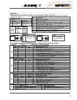
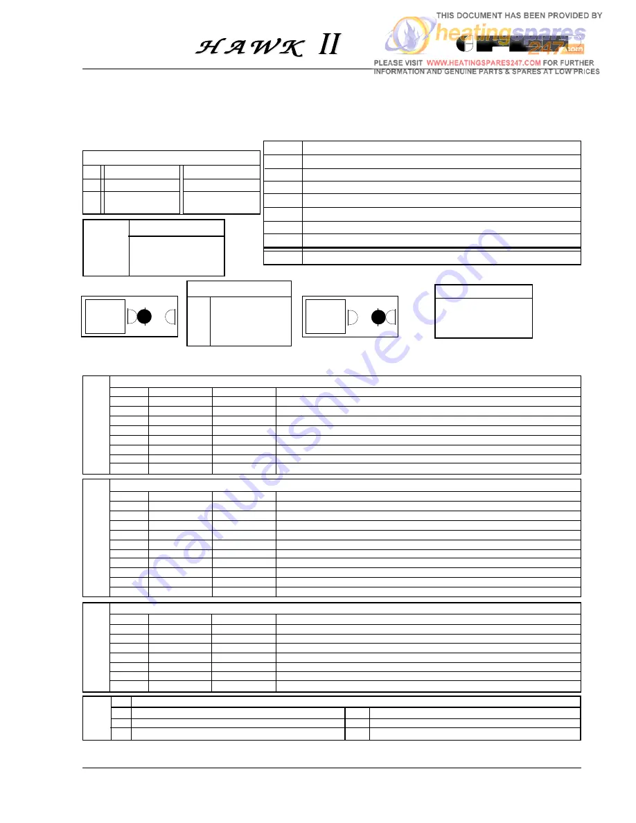
General Notes

*The pilot light should only be ignited after the Fan (16) has run for at least 20 seconds on full speed.
*The central heating pump (32) will run to disperse heat if the temperature at the heat exchanger limit thermostat (50) is too high
*Fuse on P.C.B.: 2 Amp.

LED  n

°

signification:

1

Mains on/low voltage on

2

Flowmeter (136) on

3

Central heating room thermostat (72) / clock (62) calling

4

Sensor (34) or (42) calling for heat

5

Central Heating waiting time, max. 3 minutes  delay following shut off
Boilerstat (63), Clock (62), Roomstat (72) or use of Hot Water

6

Demand for heat - relay (RY2) will be energised

7

Air pressure switch (43) on, air flow checked

  Jumpers JP1 - JP4

Fitted

Not fitted

JP1

No waiting time

Waiting time on

JP4

Fan control

Fan control

High & Low speed

High speed only/off

temp.

Ohm

10

°

 C

890 ohm

25

°

 C

1000 ohm

60

°

 C

1300 ohm

80

°

C

1490 ohm

Temp.
sensor

RY not energised

RELAY  RY

RY1

central heating pump

RY2

on/off relay

RY3

-

RY4

fan

RY energised

Note

If RY1 is not energised
the Central Heating pump
will run

Check operation using LED's as a fault finding guide.  First check section A, then B, then C, then D.
0 = LED off

1 = LED on

x = LED either on/off is not important

  Domestic Hot water tap open

(Flow rate greater than 2,5 l/min)

   LED

OK

FAULT

POSSIBLE CAUSE OF FAULT

1

1

0

No mains electricity/switches off/fuse blown.

2

1

0

D.H.W. flowmeter (136) not operating.

3

X

X

Not required for D.H.W.

4

1

0

- D.H.W. sensor (42) not connected or D.H.W. temperature too high

5

0

1

- Waiting time operating: replace P.C.B.

6

1

0

Short circuit on D.H.W. sensor (42) or resistance lower than 500 Ohm
- C.H. limit thermostat (50) open circuit (pump run)
- C.H. water pressure low (114 open circuit)

A

  GENERAL TEST FOR D.H.W. AND CENTRAL HEATING (First check A and B above)

LED/REL.

OK

FAULT

POSSIBLE CAUSE OF FAULT

RY2

energised

not energised

Check first A and B above

RY4

energised

not energised

Air pressure switch (43) not in NC position or miswired:
- check wiring
- fan (16) at low speed remove jumper JP4

7

1

0

- fan (16) not running at full speed or
- air flow too low:
- air pressure switch (43) faulty

B

  CENTRAL HEATING ON                        Room stat (72) at Max, HW tap closed

   LED

OK

FAULT

POSSIBLE CAUSE OF FAULT

1

1

0

No main electricity/switches off, fuse blown.

2

0

1

Hot water tap open - D.H.W. flowmeter (136) contact closed

3

1

0

Roomstat (72) or clock (62) not calling for heat

4

1

0

- Central heating sensor (34) not connected or
- boiler temperature too high or
- boiler thermostat (61) below CH temperature

5

0

1

Waiting time still operating (max. 3 minutes)

6

1

0

- C.H. sensor (34) short circuit or resistance lower than 500 ohm
- C.H. limit thermostat (50) open circuit (pump will run)
- C.H. water pressure low (114 open circuit)

C

IGNITION OF PILOT

PUSH PIEZO IGNITER SEVERAL TIMES

1

Fan (16) should run at full speed for at least 20 seconds
(open hot tap or set controls so boiler is calling for heat).

2

Check first A, B and C above

3

Push ignition button (60) fully in

4

Check spark and position of spark electrode (24)

D

Содержание HAWK II

Страница 1: ...LED COMBINATION BOILER SERVICE HELPLINE FOR SERVICE OR TECHNICAL ASSISTANCE PHONE 08707 282 885 PLEASE QUOTE BOILER SERIAL NUMBER Leave these instructions with the user Important Please read this book before installing this appliance INDUSTRIE W R C No 9207076 01 01 ...

Страница 2: ...d carton 14 Installation dimensions 15 4 Preparing the Flue Assembly 16 5 Connecting the Boiler 17 6 Fitting the Flue Assembly 17 7 Electrical Installation 18 8 Commissioning Testing 18 8 1 Filling the Central Heating System 18 8 2 Filling the Domestic Hot Water System 18 8 3 Electricity Supply 18 8 4 The Gas Installation 19 8 5 To Light the Boiler 20 8 6 To Range Rate the Boiler C H 21 Gas pressu...

Страница 3: ...f the domestic hot water although a one second pump spin will automatically cut in when the domestic hot water is shut off thus preventing failure of the pump due to sticking in the summer months A permanent pilot is used to provided ignition for the main burner this is lit by the use of a piezo igniter The boiler is designed to be used with an external time switch room thermostat of voltage free ...

Страница 4: ... 50 Hz External fuse 2 A Electrical Input 150 W Central Heating Max Flow Temperature 85 C Temperature Rise Across Boiler 20 C Domestic Hot Water Flow 35 C Rise 9 2 litres min Minimum Domestic Hot Water Flow 2 5 litres min Maximum Domestic Cold Water Inlet press 10 bar Minimum Heating Circuit Pressure 0 8 bar Maximum Heating Circuit Pressure 3 0 bar Low water pressure switch 0 4 bar Boiler Water Ca...

Страница 5: ... Cold Water inlet 5 Central Heating Pressure relief valve 6 Central Heating Flow outlet 7 Central Heating Return inlet 8 Air intake for two pipe flue systems FRONT VIEW LEFT SIDE VIEW REAR VIEW TOP VIEW 480 900 370 77 5 50 75 80 50 50 97 5 1 2 3 4 5 6 7 40 85 242 235 60 100 Ø i 9 2 Øi82 1 2 0 242 1 2 6 5 235 160 157 480 ...

Страница 6: ...INDUSTRIE 6 Boiler Flow Diagram Fig 2 ...

Страница 7: ...6 Automatic air vent 37 Cold water inlet filter 39 Cold water flow limiter 40 Domestic hot water expansion vessel optional 42 D H W temperature sensor 43 Air pressure switch 44 Combination gas valve 45 Knob gas valve 46 Operator gas valve 47 Modulating regulator Modureg gas valve 48 Burner pressure test point 49 Overheat cut off thermostat 50 Central heating limit thermostat 52 D H W limit thermos...

Страница 8: ...ugh particular attention is draw to the requirements of the current i e wiring regulations and in Scotland the electrical provisions of the building regulations applicable in Scotland with respect to the installation of the combination boiler in a room or internal space containing a bath or shower Where a room sealed appliance is installed in a room containing a bath or shower any electrical switc...

Страница 9: ...9 INDUSTRIE TerminalPosition Minimum Clearance mm NOTES Access to the front of the boiler must be available for maintenance min 600 mm Fig 5 Fig 3 ...

Страница 10: ...be drained down The drain taps should be in accordance with BS2879 Copper tubing to BS2871 Part 1 is recommended for water carrying pipework Pipework in horizontal runs should have a gradient where possible to facilitate the removal of air It should be ensured that the boiler heat exchanger is not a natural point for collecting air A typical heating system with domestic hot water circuit is illust...

Страница 11: ...hout Key 1 Filling point C H 2 Temporary connection 3 Cold water supply TEMPORARY FILLING LOOP A temporary filling loop of the above type conforming to WRC approval should be installed between the cold water mains and the central heating system Fig 6 Gas Cold water Additional expansion vessel C H if required Filling point C H Bypass ...

Страница 12: ...ION VESSEL VOLUME litres LITRES 25 3 5 6 5 13 7 4 7 10 3 8 3 50 7 0 12 9 27 5 9 5 20 6 16 5 75 10 5 19 4 41 3 14 2 30 9 24 8 100 14 0 25 9 55 1 19 0 41 2 33 1 125 17 5 32 4 68 9 23 7 51 5 41 3 150 21 0 38 8 82 6 28 5 61 8 49 6 175 24 5 45 3 96 4 33 2 72 1 57 9 200 28 0 51 8 110 2 38 0 82 4 66 2 0 140 0 259 0 551 0 190 0 412 0 33 For syst volumes other than those given above mult the syst volume by...

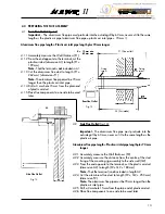
Страница 13: ...be obtained with the fixing bolts supplied use alternative fixings 3 0 PREPARING APPLIANCE FIXING Side Flue Applications 3 1 Select the boiler location carefully ensuring that all the requirements given in previous text are satisfied Fig 10 will give guidance 3 2 Mark position of flue centre and fixing bolts as shown in figure 10 3 3 Carefully out the circular flue hole 118 mm minimum diameter 3 4...

Страница 14: ... Always use two spanners to prevent twisting of soft copper pipework Note The central heating safety valve 5 should be piped 15 mm to discharge safely outside the property 1 Electrical cable entry 2 Gas supply 3 Domestic Hot Water outlet 4 Domestic Cold Water Inlet 5 Outlet Central Heating safety valve 6 Central Heating flow outlet 7 Central Heating return inlet 2 22 mm 3 4 5 15 mm 6 7 22 mm Side ...

Страница 15: ... be used later Side Flue Outlet Fig 13 4 2 Side Flue Outlet fig 13 Important The aluminium flue pipe must protrude into the outside grill by 60 mm never cut it to the same length as the plastic air pipe Aluminium flue pipe length Plastic air inlet pipe length plus 70 mm longer 4 2 1 Accurately measure the Wall thickness P2 4 2 2 Accurately measure the distance from the centre of the stud fixing of...

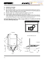
Страница 16: ...llation pipe work to boiler valves in the order shown in fig 11 5 5 Connect the pressure relief valve discharge pipe 15 mm to the outside of the building where possible over a drain The discharge must be such that it will not be hazardous to occupants or passers by cause damage to external electric components or wiring The pipe should be directed towards the wall It must not discharge above an ent...

Страница 17: ...pply cable must be no less than 0 75 mm 24x0 2 mm to BS6500 table 16 7 1 2 The earth conductor must be cut longer than the live and neutral fig 19 Connect the Supply Cable to the terminal block marked 240 V 50 Hz L N the supply cable is to be connected as follows i Connect the brown wire to the L live terminal ii The blue wire to the N neutral terminal iii The green yellow wire to the earth termin...

Страница 18: ... Tighten cap on heat exchanger air vent Ensure the working pressure when filled is between 1 to 1 5 bar on the pressure gauge see technical data Check the system for leaks Flush out system in accordance with B S 7593 8 2 Filling the Domestic Hot Water System Close all hot water draw off points Open main cold water stop cock and ensure the cold water inlet cock is open at the boiler jig bracket fig...

Страница 19: ...ress gas control knob 1 fully and keep depressed 7 Press igniter botton 2 repeatedly until pilot flame lights View through pilot inspection window 5 8 Once pilot flame is lit keep gas control knob fully depressed for 20 seconds 9 Release gas control knob 1 and main burner will light Notes After using hot water the central heating will not light for at least two minutes Domestic hot water is availb...

Страница 20: ... 1 2 P1 X3 6 5 3 4 1 F1 9 8 7 6 5 4 3 2 1 X8 1 2 3 4 5 6 7 8 9 X5 1 2 X7 JP4 13 L7 RY2 RY4 JP1 P2 P2 P1 MIN MAX MIN MAX Note 1 Modulation is available on central heating so the procedures must be carried out while the system is relatively cold Recheck boiler thermostat is set to maximum d Adjust the potentiometer P1 on the PCB fig 24 in the control panel until the required burner pressure is obtai...

Страница 21: ...en sleeve lock but F then check that the pressure is still at the required value 11 Adjust minimum pressure by rotating screw E anticlockwise until the required value is reached 12 Fit coil C by sliding it into the sleeve pushing and rotating it lightly until the coupling spring I clicks into place 13 Shut down and ignite the burner checking that the minimum pressure value is stable 14 Reconnect t...

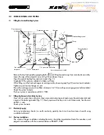
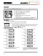
Страница 22: ... this will come into operation when the selector switch is turned to the position marked heating timed and hot water To set time of day 1 Slide switch A to left position 2 Using button and adjust until the correct time is shown on display B Pre Set Programmes The timer is pre programmed with 3 ON and 3 OFF times 6 30 8 30 12 00 12 00 16 30 23 30 6 30 1 6 00 1 8 30 2 9 00 2 If these are suitable no...

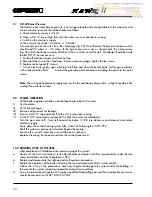
Страница 23: ...ign will be shown in the display window B Reset Button By the use of a pencil the reset button can be pushed R This will clear all programmes apart from those factory pre set Reset is only possible with switch A in set Clock position x 8 8 REMOVAL OF THE CLOCK a Refer to section 1 items a c d f and j b Disconnect the electrical connections to the time clock c Remove the time clock from the control...

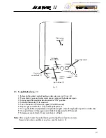
Страница 24: ... at least 9 0 SYSTEM OPERATION Let the boiler operate normally on central heating for about 30 minutes I Vent radiators II Vent heat exchanger III Examine all pipework for leakage IV Turn on a D H W tap and check that the C H pump stops running V As the D H W temperature reaches 60 C check the burner for modulation Turn the gas valve off twist left hand white button 1 12th turn clockwise and relea...

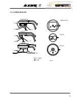
Страница 25: ...g 46 BLUE BLACK BLACK 1 2 BLACK DL 1E BROWN BLUE 3 3 1 1 2 KROMSCHRODER HUBA 605 2 1 3 BROWN BLUE 3 BROWN KROMSCHRODER HUBA 602 1 2 2 3 HUBA 605 HUBA 602 2 3 1 Brown Common Black N C Blue N O 11 0 AIR PRESSURE SWITCH ...

Страница 26: ...ump 34 386818 800310 2 Temperature sensor 36 394246 801160 1 Automatic air vent 39 386829 801220 1 Cold water flow limiter 43 379351 800140 1 Air pressure switch 44 372544 803450 1 Combination gas valve 49 386815 801240 1 Overheat cut off thermostat 50 386577 800160 1 Heatexchangerlimitthermostat 101 803410 1 P C B VMF7 112 386573 810570 1 Pilot injector Natural Gas 112 810660 1 Pilot injector L P...

Страница 27: ...estic Hot Water Performance Fig 1 D H W Pressure Drop VS flow A Standard with col water Flow Restricter B Cold Water Flow Restricter Removed Fig 1 Fig 2 D H W temperatureVS flow A Cold Water 15 C B Cold Water 5 C Fig 2 ...

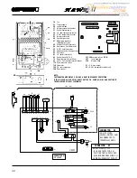
Страница 28: ...ob gas valve 62 Time clock 63 C H boiler thermostat 68 Control box with P C B 72 Room thermostat not fitted 80 240V 24V roomstat terminal blocks 114 Water pressure switch 136 Flowmeter 145 C H pressure gauge 156 Piezo igniter SHORT CIRCUIT 12 13 BOILER STARTS FOR C H WAITING TIME IS EXCLUDED MAX BURNER PRESSURE C H CAN BE CHEDKED SET WITH P1 CONNECTOR X3 A D H W FLOW SWITCH ON OFF CAN BE CONNECTED...

Страница 29: ... 3 X X Not required for D H W 4 1 0 D H W sensor 42 not connected or D H W temperature too high 5 0 1 Waiting time operating replace P C B 6 1 0 Short circuit on D H W sensor 42 or resistance lower than 500 Ohm C H limit thermostat 50 open circuit pump run C H water pressure low 114 open circuit A GENERAL TEST FOR D H W AND CENTRAL HEATING First check A and B above LED REL OK FAULT POSSIBLE CAUSE ...

Страница 30: ......

Страница 31: ......

Страница 32: ...INDUSTRIE ALL SPECIFICATIONS SUBJECT TO CHANGE PO BOX 3774 SUTTON COLDFIELD WEST MIDLANDS B76 8BH Tel 08707 282 885 Cod 3540258 3 01 01 ...

Отзывы: