


MOUNTING AND WIRING
CAUTIONS:
1. Ceramic insulators should nor be in or close to the flame.
2. Electrode assemblies should not be adjusted or disassem bled.
Electrodes should have a gap spacing of 0.125± 0.031 in
(3.12± 0.81 mm). If this spacing is not correct, the assembly must
be replaced. Electrodes are NOT field adjustable.
3. Exceeding the temperature limits can cause nuisance lockouts and
premature electrode failure.
4. Electrodes must be placed where they could not be exposed to the
appliance user in normal operation.
SEQUENCE OF OPERATION / FLAME
RECOVERY / SAFETY LOCKOUT
Power Up/Stand-By
• Upon applying power (24 VAC) to 24V terminal, the control will
reset, perform a self check routine, initiate full time flame sensing,
flash the diagnostic LED for up to four seconds, and enter the
thermostat scan state.
Heat Mode
• When a call for heat is received from the thermostat supplying 24
volts to TH/W, a pre-purge delay begins, then the gas valve is
energized and the sparks commence at both burners for the trial
for ignition period.
• When flame is detected during the trial for ignition, sparks are
shutoff immediately and the gas valve remains energized. The
thermostat and burner flame are constantly monitored to assure
the system continues to operate properly. When the thermostat
is satisfied and the demand for heat ends, the main valve is
de-energized immediately.
Failure to Light - Lockout
SINGLE TRIAL MODEL
Should either burner fail to light, or flame is not detected during the
trial for ignition period, the control will go into lockout and the valve
will be turned of immediately.
MULTI TRIAL MODEL
Should either burner fail to light, or flame is not detected during
the first trial for ignition period, the gas valve is de-energized
and the control goes through an interpurge delay before another
ignition attempt. The control will attempt two additional ignition
trials before going into lockout and the valve relay will be de-
energized immediately.
Recovery from lockout requires a manual reset by either resetting
the thermostat or removing 24 volts for a period of 5 seconds.
FLAME FAILURE- RE-IGNITION
If the established flame signal is lost from either burner while the
burners are operating, the control will respond within 0.8 seconds.
The HV spark will be energized for a trial for ignition period in an
attempt to relight the burners. If either burner does not light the
control will de-energize the gas valve. Multi-try models will make
two more attempts to relight the burners. If either burner does not
relight the control will go into lockout as noted above in “Failure
to light”. If flame is re-established, normal operation resumes.
Flame Fault
If at any time the main valve fails to close completely and main
tains a flame, the full time flame sense circuit will detect it and
flash an error code of 2.
CAUTION:
Label all wires prior to disconnection when servicing controls.
Wiring errors can cause improper and dangerous operation.
A functional checkout of a replacement control is recommended.
WARNING:
Operation outside specifications could result in failure of the
Fenwal product and other equipment with injury to people
and product.
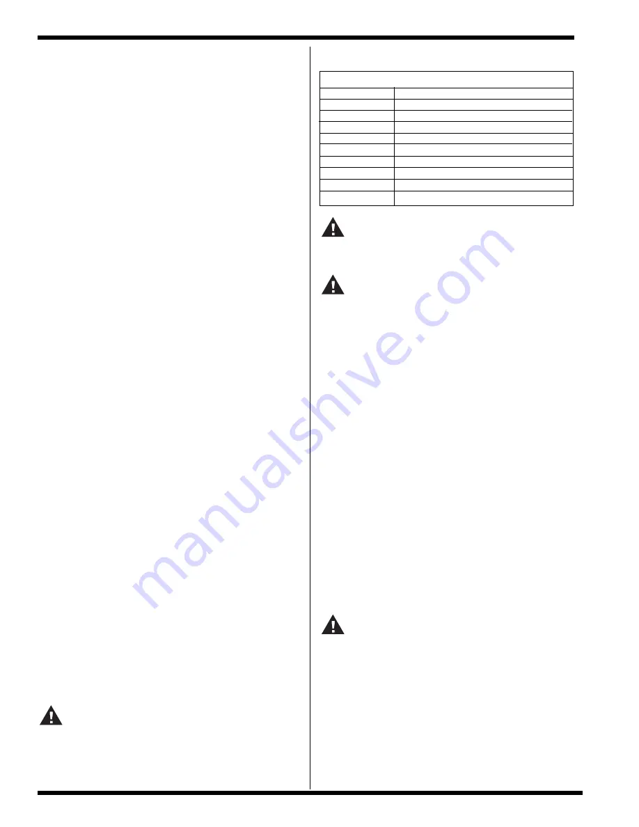
TERMINAL DESIGNATIONS
TH/W
THERMOSTAT INPUT
GND
SYSTEM GROUND
V1
VALVE POWER
V2
VALVE GROUND
NC
ALARM
S1
REMOTE FLAME SENSOR
S2
REMOTE FLAME SENSOR
FC1
FLAME CURRENT TEST PIN
FC2
FLAME CURRENT TEST PIN
24V
24 VAC INPUT (FULL TIME)
WARNING:
The Series 35-62 uses voltages of shock hazard potential. Wiring
and initial operation must be done by a qualified service technician.
The Series 35-62 is not position sensitive and can be mounted
vertically or horizontally. The control may be mounted on any
surface with #6 sheet metal screws.
All wiring must be done in accordance with both local and
national electrical code. The control must be secured in a area
that will experience a minimum of vibration and remain below the
maximum operating temperature of 160°F.
All connections should be made with UL approved 105°C rated
18 gauge, stranded,.054 thick insulated wire. Refer to wiring
diagram when connecting the Series 35-62 to other components
in the system.
PROPER ELECTRODE LOCATION
Proper location of the electrode assembly is important for
optimum system performance. It is recommended that electrode
assembly be mounted temporarily using clamps or other suitable
means so that the system can be checked before permanently
mounting the assembly. The electrode assembly should be
located so that the tips are inside the flame envelope and about
1/2 inch (1 cm) above the base of the flame. See Figure 3.
Page 2
Series 35-62, 24 VAC Dual Point DSI Control
www.fenwalcontrols.com
1-800-FENWAL-1


