www.fennerdrives.com
For technical assistance,
please call +1-717-665-2421
B-LOC®
Keyless Bushings provide a high capacity, zero-backlash shaft/hub or
coupling connection by means of a mechanical interference fit. Please follow
these INSTALLATION AND REMOVAL INSTRUCTIONS carefully to ensure
proper performance of this
B-LOC
® unit.
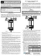
INSTALLATION
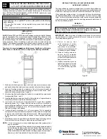
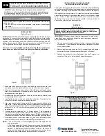
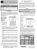
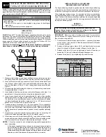
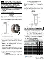
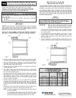
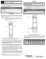
(Refer to Figure 1)
B-LOC®
Series B103 and B106 Keyless Bushings are supplied lightly oiled and
ready for installation. They are self-centering and fit straight-thru hub bores. Note
that Series B103 units permit axial hub movement during installation. In contrast,
the extended flange on Series B106 units results in an axially fixed hub position
during assembly. When reinstalling a used unit, make sure that all slits are
aligned. The frictional torque capacity of these devices is based on a coefficient
of friction of 0.12 for lightly oiled screw, taper, shaft and bore contact areas.
Therefore, it is important not to use Molybdenum Disulfide (e.g., Molykote,
Never-Seeze or similar lubricants) in any Keyless Bushing installation.
1. Make sure that locking screw, taper, shaft and bore contact areas are clean
and lightly oiled with a light machine oil and that all collar slits are aligned.
2. Loosen all locking screws by a minimum of four (4) turns and transfer at
least three (3) screws into push-off threads in order to keep Parts 1 and 2
separated during assembly (see Figure 2).
3. After inserting Keyless Bushing into hub bore, relocate locking screws used
for separating Parts 1 and 2.
4. Hand tighten locking screws and confirm that collar Item 1 is parallel and in
full contact with face of part to be attached to shaft.
5. Use torque wrench and set it approximately 5% higher than specified
tightening torque (Ma). Tighten locking screws in either a clockwise or
counterclockwise sequence (it is not necessary to tighten in a diametrically
opposite pattern), using only 1/4 (i.e., 90°) turns for several passes until 1/4
turns can no longer be achieved.
6. Continue to apply overtorque for 1 to 2 more passes. This is required to
compensate for a system-related relaxation of locking screws since tightening
of a given screw will always relax adjacent screws. Without overtorquing,
an infinite number of passes would be needed to reach specified tightening
torque.
7. Reset torque wrench to specified torque (Ma) and check all locking screws.
No screw should turn at this point, otherwise repeat Steps 6 and 7.
NOTE:
1. It is not necessary to re-check tightening torque after equipment has
been in operation.
2. The torque capacity of these units can be increased by approximately
25% by thoroughly cleaning the shaft and Keyless Bushing bore of any
lubricant. In applications subject to extreme corrosion, the slits in all
collars should be sealed with a suitable caulking compound or equivalent.
Likewise, push-off threads should be protected from corrosion.
INSTALLATION OF B-LOC® KEYLESS BUSHING
OVER SHAFT KEYWAYS
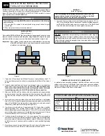
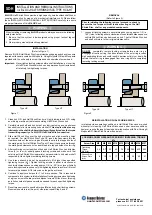
The Keyless Bushing should be positioned so that slits in Keyless Bushing
collars that contact the shaft are located approximately opposite the keyway.
In addition, a locking screw should be centered directly over the keyway.
When tightening locking screws, it is important to follow the installation
procedure outlined above, which specifies equal 1/4 turns of each locking
screw. Failure to follow these instructions could result in excessive tightening
of the screw over the keyway, possibly causing permanent deformation of
the Keyless Bushing collars.
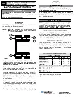
REMOVAL
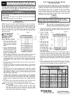
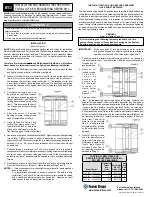
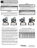
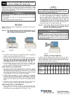
(Refer to Figure 2)
Prior to initiating the following removal procedure, check to
ensure that no torque or thrust loads are acting on the Keyless
Bushing, shaft or any mounted components.
IMPORTANT!
Make sure ends of locking screws used for removal are
ground flat and are slightly chamfered to prevent damage to screw and
collar threads during push-off.
1. C h e c k t o e n s u r e t h a t
axial movement of collars
- necessary for release of
connection - is not restricted.
Likewise, ensure that push-off
threads are in good condition.
2. Relax all locking screws by
approx. four (4) complete
turns and transfer screws to
all push-off threads located in
flange of collar Item 1.
3. Release connection by evenly
tightening all push-off screws
(not exceeding 1/4 turns)
in a diametrically opposite
sequence.
©2012 Fenner Drives B-PR-014 9/17/2012
LOCKING SCREW SIZES AND SPECIFIED
TIGHTENING TORQUE M
a
Metric Series
Inch Series
Tightening
Torque
Ma
(ft lb)
Screw
Size
Hex
Key
Size
(mm)
B106 B103
20 x 47 to 40 x 65
3/4
to 1-1/2
12
10
M6
5
45 x 75 to 65 x 95
1-5/8
to 2-9/16
30
25
M8
6
70 x 110 to 95 x 135 2-11/16 to 3-3/4
60
50
M10
8
100 x 145 to 120 x 165 3-15/16 to 4-3/4
105
90
M12
10
130 x 180 to 200 x 260 4-15/16 to 8
166
135
M14
12
220 x 285 to 260 x 325
257
219
M16
14
280 x 355 to 300 x 375
350
290
M18
14
320 x 405 to 340 x 425
500
420
M20
17
360 x 455 to 400 x 495
675
560
M22
17
INSTALLATION AND REMOVAL INSTRUCTIONS
FOR
B-LOC
®
KEYLESS BUSHING SERIES B106 & B103
B106
B103
Figure 2
WARNING
When installing or removing
B-LOC
®
products, always adhere to the following
safety standards:
1. Be sure that the system is de-energized using proper lockout/tagout
procedures.
2. Wear proper personal protective equipment.
Figure 1


