IA // ROUTING MANUAL
17
IA with SRAM eTap Wireless Electronic Drivetrain
PARTS
(2) Brake hoses
(1) SRAM eTap BLIP unit
(1) SRAM eTap CLIC unit
(1) SRAM eTap AXS BlipBox
(2) Felt 8mm grommet plug
NOTE
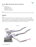
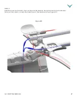
In the following diagrams, blue components are electronic wires, and red components are brake hoses.
SHIFTERS
STEP 1
Start by routing the electronic shift wires into the basebar ends (where your brake levers will even-
tually go). See Figure C1. Then continue routing into the stem, and then connect them to the BlipBox
located under the front cover. Next, route the electronic shift wires through the aerobar extensions and
then into the stem. Connect them to the BlipBox box located under the front cover. If necessary, follow
SRAM’s instructions for pairing the eTap AXS BlipBox to the front and rear derailleurs.
Figure C1


