Предлагаем вам бесплатное скачивание дополнения к руководству владельца для продукта Felt IA. Здесь вы можете найти полезное руководство, которое поможет вам лучше освоиться с вашим устройством. Не забудьте скачать его с manualshive.com.
IA // ROUTING MANUAL
IA DISC (1.0)
OWNER’S MANUAL SUPPLEMENT
SHIFT & BRAKE ROUTING
Страница 1: ...IA ROUTING MANUAL IA DISC 1 0 OWNER S MANUAL SUPPLEMENT SHIFT BRAKE ROUTING...
Страница 2: ...e mechanics as well as special tools If you are not a highly skilled or experienced bicycle mechanic we strongly recommend you take your bicycle to an authorized Felt Bicycles retailer in order to obt...
Страница 3: ...2 5mm flat grommet NOTE In the following diagrams blue purple and green components are electronic wires and red compo nents are brake hoses SHIFTERS STEP 1 Start at the basebar See Figure A1 Using a S...
Страница 4: ...the front cover connect a 1200mm wire to it and route through the stem and into the frame where the top tube mounted storage box is located Then continue routing through the downtube to Junction B bo...
Страница 5: ...om bracket shell Connect an electronic wire 300mm shown in green in Figure A3 from Junction A RS910 to the battery Connect a wire 300mm from the Junction B box located near the bottom bracket to the f...
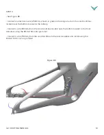
Страница 6: ...ear brake caliper Have the brake hose enter the non drive side chainstay and route over the bottom bracket shell Then feed the hose up through the downtube See Figure A4 Figure A4 STEP 2 Exit where th...
Страница 7: ...eadtube cover is removed for easier access and visibility Using the correct length of hose see Appendix A Wire Hose Lengths start by routing the front brake hose into the fork and feed the hose upward...
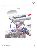
Страница 8: ...OUTING MANUAL 8 STEP 2 Feed the hose into the stem then out and into the basebar Route the hose to the brake lever Here you ll be able to connect the brake hose to the brake lever See Figure A7 Figure...
Страница 9: ...ps are the same See Figure A8 Using a Shimano Y E tube connector Shimano part number EW JC130 connect its two electronic shift wires located where the brake levers will go and connect to the Junction...
Страница 10: ...t grommet NOTE In the following diagrams blue purple and green components are electronic wires and red compo nents are brake hoses SHIFTERS STEP 1 Start at the basebar See Figure B1 Using a Shimano Y...
Страница 11: ...gram to the Junction A box located under the front cover and route through the stem and into the frame where the top tube mounted storage box is located Then continue routing through the downtube to J...
Страница 12: ...tion B box located near the bottom bracket to the battery Connect a wire 300mm from the Junction B box located near the bottom bracket to the front derailleur using the 8mm 2 5mm flat grommet Connect...
Страница 13: ...rear brake caliper Have the brake hose enter the non drive side chainstay and route over the bottom bracket shell Then feed the hose up through the downtube See Figure B4 Figure B4 STEP 2 Exit where t...
Страница 14: ...headtube cover is removed for easier access and visibility Using the correct length of hose see Appendix A Wire Hose Lengths start by routing the front brake hose into the fork and feed the hose upwar...
Страница 15: ...OUTING MANUAL 15 STEP 2 Feed the hose into the stem then out and into the basebar Route the hose to the brake lever Here you ll be able to connect the brake hose to the brake lever See Figure B7 Figur...
Страница 16: ...eps are the same See Figure B8 Using a Shimano Y E tube connector Shimano part number EW JC130 connect its two electronic shift wires located where the brake levers will go and connect to the Junction...
Страница 17: ...1 Start by routing the electronic shift wires into the basebar ends where your brake levers will even tually go See Figure C1 Then continue routing into the stem and then connect them to the BlipBox l...
Страница 18: ...d enter the non drive side chainstay Route over the bottom bracket shell and feed the hose through the downtube See Figure C2 Figure C2 STEP 2 Exit where the integrated storage compartment is position...
Страница 19: ...ake sure that your frame s front headtube cover is removed for easier access and visibility Start by routing the front brake hose into the fork and feed the hose upwards See Figure C4 The hose should...
Страница 20: ...ANUAL 20 STEP 2 Feed the hose up into the stem then out of the stem and into the basebar Route the hose to the brake lever Here you ll be able to connect the brake hose to the brake lever See Figure C...
Страница 21: ...s corresponding lever Start by routing the electronic shift wires into the basebar ends where your brake levers will eventually go Then continue routing through the basebar and down into the integrate...
Страница 22: ...es SHIFTERS DERAILLEURS NOTE In the following diagrams blue components are shifter cables and red components are brake hoses STEP 1 Start by cutting two 2 pieces of housing for the left and right exte...
Страница 23: ...A Park Tool IR 2 specialty tool is very helpful when doing some of the next steps but is not necessary STEP 3 Remove the rear cover from the frame s seat tube to gain more visible access to the housin...
Страница 24: ...e removable top tube box and into the frame See Figure D4 Then continue routing above the bottom bracket and through the drive side chainstay and out the rear exit hole near the rear derailleur See Fi...
Страница 25: ...ttom bracket shell and feed the hose through the downtube See Figure D6 Figure D6 STEP 2 Exit where the integrated storage compartment is positioned along the top tube Route through the stem and then...
Страница 26: ...ake sure that your frame s front headtube cover is removed for easier access and visibility Start by routing the front brake hose into the fork and feed the hose upwards The hose should exit behind th...
Страница 27: ...OUTING MANUAL 27 STEP 2 Feed the hose into the stem then out towards the basebar Route the hose to the brake lever Here you ll be able to connect the brake hose to the brake lever See Figure D9 Figure...
Страница 28: ...ar please note the following diagram in regards to routing cables and hoses in and around the bar all other steps are the same See Figure D10 Route the brake hose through the stem and into the base ba...
Страница 29: ...850MM 1 RIGHT LEVER REAR BRAKE R HD T910 34SS 1700MM 1 58CM LEFT LEVER FRONT BRAKE L HD T910 70SS 850MM 1 RIGHT LEVER REAR BRAKE R HD T910 34SS 1700MM 1 Mechanical 48CM 51CM Rear shfiter aduster to re...