background image

Page 9

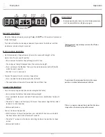
Upper stop position 

•  To set the upper stop position (the maximum height of the table): 


— Raise or lower the table to the desired maximum height.


— Press and hold S, then press and hold 3. Continue to press both buttons for about 3 

seconds.


— The letter “L” appears on the display. This means the maximum height of the table is 

locked at its current position.


— Release both buttons.

•  To erase the upper stop position:


— With the table at its upper stop position, press and hold S, then press and hold 2

Continue to press both buttons for about 3 seconds.


— The letter “C” appears on the display, indicating the upper stop position has been 

erased.


— Release both buttons.

Changing the height display units 

•  To change the display units from centimeters to inches or from inches to centimeters: 


— Press and hold S, then press and hold the DOWN 

 button. Continue to press both 

buttons for about 3 seconds.


— The height information will change between centimeters and inches.


— Release both buttons.

Adjusting the height readout 

•  To set the display height of the table to account for different worksurface thicknesses:


— Move the table to the lowest position by pressing the DOWN

 button.


— Measure and record the height of the top of the worksurface.


— Press and hold S until the first LED number blinks.


— Press and hold UP 

 or DOWN 

, changing the number in the first LED position to  

the number desired.


— Press and hold S again until the second LED number blinks.


— Press and hold UP 

 or DOWN 

, changing the number in the second LED position  

to the number desired.


— Press and hold S again until the third LED number blinks.


— Press and hold UP 

 or DOWN 

, changing the number in the third LED position to 

the number desired.


— Finish setting this new height readout by pressing S one more time.

•  The new height readout is now ready to use.

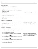
In inch format, the minimum adjustable amount (third 

digit) is 0.5". (The third digit will be either 0 or 5.) In 

centimeter format, the minimum adjustable amount (third 

digit) is 1 cm. (The third digit will be 0 through 9.)

There are 2.54 centimeters per inch. This makes it easy 

to tell what the current display units are. For example, if 

the table is about three feet high, the display will read 

approximately either 36.0 (inches) or 090 (centimeters).

If there is a memory stop position higher than the upper 

stop position, the memory stop will be erased.

TriumphLX Operation

Содержание esi Triumph LX

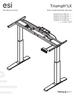
Страница 1: ...Assembly instructions Triumph LX Model 2T LX C36 24 ___ Model 2T LX C36 30 ___ Model 2T LX C48 24 ___ Model 2T LX C48 30 ___ ___ SLV BLK or WHT Electric height adjustable table base...

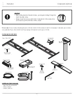
Страница 2: ...river Phillips 1 and 2 bits caution When drilling holes for the wood screws guard against drilling through the top of the worksurface Always check that screws used to attach components to the worksurf...

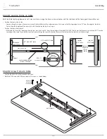
Страница 3: ...eep position the rear cross channel 6 5 from the rear edge of the table With 30 0 tables position the rear cross channel 9 5 from the rear edge of the table These positions of the frame will align the...

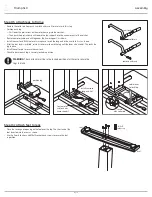
Страница 4: ...leg under the frame support as shown Install the cam lock With the lever arm upward insert the long end of the cam lock first as shown After the cam lock is installed rotate its lever arm toward the...

Страница 5: ...keypad can reach the control unit and the motor cables can extend from the control unit to both motors Attach the control unit using the two M5x15 2 Phillips round head screws Step 7 make cable and c...

Страница 6: ...ess the UP and DOWN buttons individually to test operation End your test with the legs lowered Unplug the power cord If there are problems with operation check that all cable and cord connections are...

Страница 7: ...to ensure free unobstructed movement If necessary adjust the leveling glides on the feet to level the worksurface Plug the power cord into an AC outlet Re initialize the system See Step 8 on page 6 IM...

Страница 8: ...worksurface to a memory stop position Press and hold the desired memory button 1 2 or 3 The worksurface will move to the saved position and then stop Lower stop position To set the lower stop position...

Страница 9: ...ace thicknesses Move the table to the lowest position by pressing the DOWN button Measure and record the height of the top of the worksurface Press and hold S until the first LED number blinks Press a...

Страница 10: ...is no gyro sensitivity Press and hold the S button for more than 3 seconds This completes the adjustment Error codes If one or more motors are changed in a system the table must be reset to factory s...

Страница 11: ......

Страница 12: ...anty or any implied warranty and the purchaser s sole remedy is limited to the repair or replacement at ESI s option of the product or any defective part Costs such as installation labor fees or expre...

Отзывы: