background image

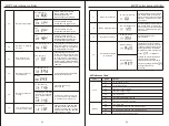
Action                Instruction                       LCD display

Long press“Down”button until the icon in
the red box in the right picture flashes, 
indicating that the inverter is trying to 
communicate with MPPT. The icon 
disappears after the inverter loosens 
the button for 10 seconds.

Matching 
MPPT 
function is 
prohibited

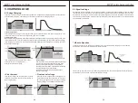
8.3 Matching MPPT function successfully enabled:

Action                Instruction                       LCD display

If MPPT is in charging state

When the 

MPPT function is successfully enabled, 
the icon in the red box in the right picture 
will appear

Match MPPT

 function to enable 

successfully

If MPPT is not in the charging state, but 
PV voltage is greater than 30V and is in 
the startup state

When the MPPT 

function is successfully enabled, the 
icon in the red box in the right picture 
will appear

Match MPPT 

function to enable 

successfully

8.4 Matching MPPT function is prohibited successfully:

Action                Instruction                       LCD display

When the matching MPPT function is 
prohibited successfully

MPPT icon 

information will no longer be displayed

Match MPPT

 function

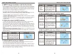
1. If the MPPT function is enabled, the 
LCD interface page turning will display 
PV voltage, power and other information

2. If the matching MPPT function is 
prohibited, the LCD interface page 
turning will not display PV voltage, 
power and other information

Whether matching 

MPPT function 

enables judgment

INPUT

V

INPUT

V

INPUT

V

INPUT

V

PV

V

19

MPPT solar charge controller

8.MPPT charger controller match to the Inverter

In actual application system, MPPT controller and inverter will charge the battery at the same 
time, the charging current will excessive to occur unsafe situation, so we add the function of 
matching the inverter to limit the charging current of the battery. However, since it needs to be 
matched with MPPT of different manufacturers , but the MPPT charging current cannot be limited. 
The current solution is to limit the charging current of the inverter.

The inverter match to the MPPT controller is mainly including two function:
1.Enabling or disable inverter to match the MPPT function. (Special attention: when upgrading 
the firmware of the inverter, it needs to disable the function matching MPPT first);

2.Limited the charging current of the inverter. The methods are as follows:
   a) When the MPPT charging current ≥ inverter setting charging current, the maximum allowable 
charging current of the inverter equal to 0;
   b) When the MPPT charging current 

< 

inverter setting charging current, the maximum allowable 

charging current of the inverter equal to inverter setting charging current subtract MPPT 
    charging current;

8.1 Match the inveter to the MPPT controller:

1.To enable the inverter to match the MPPT controller, the inverter and MPPT controller should be 
switched on first, and the communication lines between them have been connected;
2.Then press the “Down”button of the inverter for more than 2.5 seconds, until the MPPT charger icon 
flashes. At this time, you can release the button. The icon flashing indicates that the inverter is trying to 
communicate with the MPPT. The inverter is releasing. After pressing the button for 10 seconds, the 
icon stops flashing. When the communication is successful, it means that the function is successfully 
enabled.
3.After successfully enabling, the matching MPPT function flag will be saved in the EEPROM. Restarting
 the inverter does not need to be manually enabled again.
4.After successfully enabling, turning the page on the LCD screen will display MPPT PV voltage, power 
and other information.

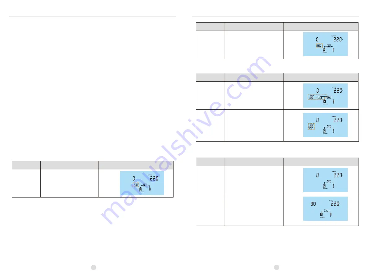
Action                Instruction                       LCD display

Long press “Down”button until the 
icon in the red box in the right picture 
flashes, indicating that the inverter is 
trying to communicate with MPPT. The 
icon stops flashing after the inverter 
loosens the button for 10 seconds.

Match the MPPT 
function enable

8.2 Matching MPPT function is prohibited:

1.To prevent the inverter from matching the MPPT function, the MPPT should be turned off or the 

communication connection between the two should be disconnected.

2.Then long press the “Down”button of the inverter for more than 2.5 second, until the MPPT charger 

icon flashes. At this point, the button can be released. The flashing icon indicates that the inverter is

trying to communicate with MPPT. The flashing icon will stop 10 seconds after the button is released. 

When communication fails, it means it is forbidden successfully.

INPUT

V

20

MPPT solar charge controller

Содержание MPPT

Страница 1: ...USER GUIDE MPPT solar charge controller MPPT solar charge controller Make life full of hope 358 010003 04 ...
Страница 2: ... 6 4 OPERATION 7 4 1 Power Up 7 4 2 Operation and Display Panel 7 4 3 LCD Display Icons 8 4 4 LCD setting 9 12 4 5 Reference Code 12 5 CHARGING LOGIC 13 5 1 3 stage Charging 13 5 2 Equalize Stage 14 5 3 Setting Parameter and Default Value 15 6 TROUBLE SHOOTING 16 7 SPECIFICATIONS 17 18 8 MPPT charger controller match to the Inverter 19 8 1 Match the inveter to the MPPT controller 19 8 2 Matching M...

Страница 3: ...rt circuit batteries or other electrical parts and could cause an explosion 8 Please strictly follow installation procedure when you want to disconnect PV or battery terminals Please refer to Installation section of this manual for the details 9 GROUNDING INSTRUCTIONS This charger should be connected to a permanent grounded wiring system Be sure to comply with local requirements and regulation to ...

Страница 4: ...below 3 1 Unpacking and Inspection Consider the following points before selecting where to install This solar charge controller is designed in IP31 for indoor applicationsonly Do not mount the unit on flammable construction materials Mount on a solid surface Install this charger at eye level in order to allow the LCD display to be read at all times For proper air circulation to dissipate heat allow...

Страница 5: ...ct switches are both turned off before connecting power wires to the charger There are no disconnecting switches inside the charger 2 Make 4 power wires first Remove insulation sleeve 10 5mm and the conductor should be plated Tin Refer to the chart below 3 Pull all wires into the wiring box The Remote Temperature Sensor and Battery Sense wires can be inside the conduit with the power conductors It i...

Страница 6: ... A battery must be connected to the controller before operating it The controller will not operate only with solar input Solar input can trigger the controller to start up when the battery is connected without pressing the button Turn on battery disconnect switch first And press operation button for a while Then it will indicate a successful start up in LCD display Turn on solar disconnect switch I...

Страница 7: ...arameter 05 is set as one of 12V 24V 48V If you want to set Lib first set the 05 battery rated voltage MPPT 45A 12 24V can t set theAbsorption voltage to 48v LIb mode can t set the AUO then set 02 to LIb AGM Setting Programs 0 0 Program Description Options Exit setting mode Escape Maximum charging current 0 1 45A Default Setting range is from 30A 45A 60A 80A 100Aor 120A Increment of each short pres...

Страница 8: ...each short press is 0 1V The value will jump back to 12 0V after 15 5V is achieved If this program is selected to modify the changeable figure will be shown as below 1 0 The maximum current of battery equalization 15A Default The setting range is from 30A 45A 60A 80A 100Aor 120A Increment of each short press is 1A The value will jump back to 30A 45A 60A 80A 100A or 120A is achieved 0 6 Battery C V ...

Страница 9: ...arge stage charge current begins to flow typically at the maximum rate of the charge source The controller will supply solar power to charge battery as much as possible 2 Absorption stage When battery charging voltage is reached to Absorption voltage point the charging stage changes from bulk charge to Absorption Constant voltage regulation is used to maintain battery voltage at the Absorption stag...

Страница 10: ...ill supply solar power to charge battery as much as possible until battery voltage raises to battery equalization voltage Then constant voltage regulation is applied to maintain battery voltage at the battery equalization voltage The battery will remain in the Equalize stage until setting battery equalized time is arrived Equalize charging time and timeout ABSORPT BULK FLOAT Equalize Voltage EQUAL...

Страница 11: ...ns Maximum Solar Input Voltage 12VDC 24VDC 48VDC PV Array MPPT Voltage Range Maximum Input Power 12V 625W 12V 625W 12V 825W 12V 1100W 12V 1375W 12V 1650W 24V 1250W 24V 1250W 24V 1650W 24V 2200W 24V 2750W 24V 3300W 48V 2500W 48V 3300W 48V 4400W 48V 5500W 48V 6600W MODEL Maximum Battery Current Nominal System Voltage 30Amps 45Amps 45Amps 60Amps 80Amps 100Amps 120Amps 12V 24V 48V DC Auto detection 14...

Страница 12: ...nverter it needs to disable the function matching MPPT first 2 Limited the charging current of the inverter The methods are as follows a When the MPPT charging current inverter setting charging current the maximum allowable charging current of the inverter equal to 0 b When the MPPT charging current inverter setting charging current themaximum allowable charging current of the inverter equal to inv...

Отзывы: