71
es
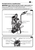
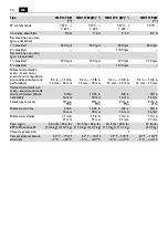
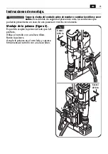
Descripción técnica y especificaciones.
Saque la clavija del enchufe antes de montar o cambiar los útiles y acce-
sorios.
Esta medida de seguridad preventiva evita los accidentes que
pudieran presentarse en caso de una puesta en marcha involuntaria.
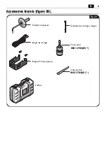
El material de serie suministrado con su herramienta eléctrica puede que no corresponda
en su totalidad al material descrito o mostrado en estas instrucciones de servicio.
ADVERTENCIA
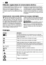
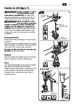
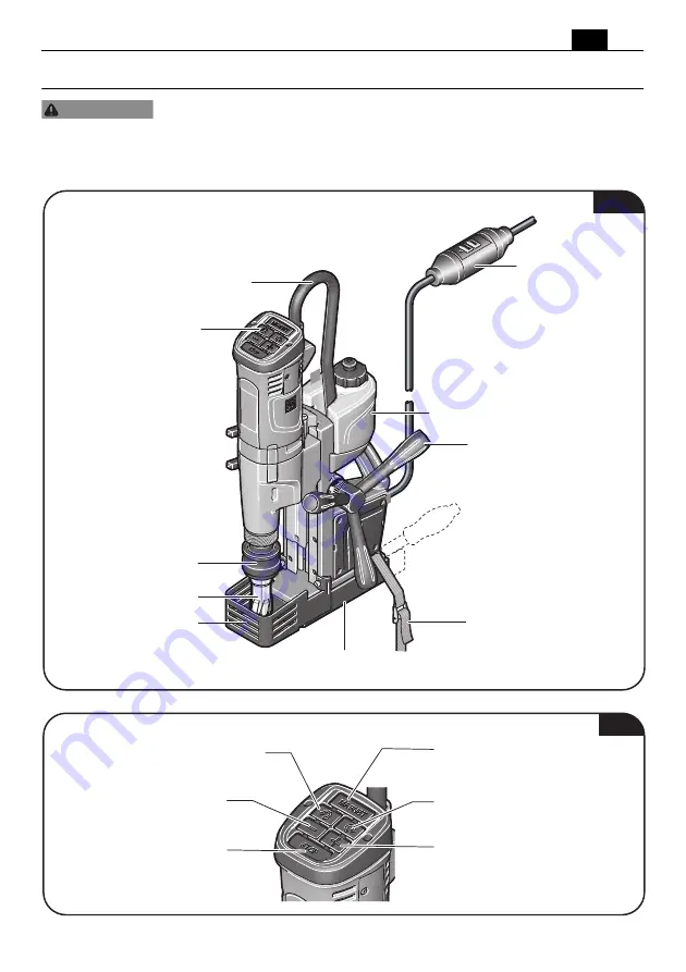
Útil
Guarda contra contacto
Portaútiles
Viseo Touch Pad
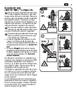
Línea del motor de taladrar
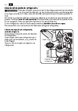
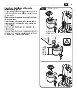
Depósito de refrigerante
Palanca
Base magnética
Cinta tensora
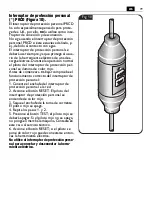
Interruptor de
protección
personal (*) PRCD
Fig. 1
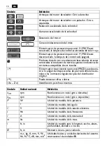
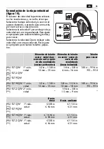
Conexión y desconexión el imán
Arranque del motor de taladrar.
Sentido de giro a derechas
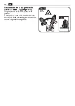
Reducción escalonada
de la velocidad
Arranque del motor de taladrar con pulsador.
Sentido de giro a izquierdas
Detención del motor
de taladrar
Aumento escalonado de la
velocidad
Fig. 2
Содержание Slugger JMU 137 QW Series
Страница 1: ...JMU 137 QW 7 270 7 273 JMU 137 MQW 7 270 7 273 JMU 137 2 QW 7 270 7 273 JMU 137 PQW 7 270...
Страница 2: ...2 Instruction Manual Mode d emploi Instrucciones de uso en 3 fr 32 es 62...
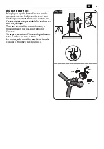
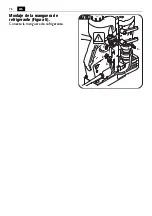
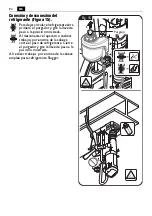
Страница 16: ...16 en Mounting the coolant hose figure 6 Connect the coolant hose 4 3 Fig 6 2 1...
Страница 76: ...76 es Montaje de la manguera de refrigerante Figura 6 Conecte la manguera de refrigerante 4 3 Fig 6 2 1...


