OBID i-scan
®
Mounting Instruction
ID ISC.ANT340/240-A / -B
FEIG ELECTRONIC GmbH
Page 25 of 28
M10101-3de-ID-B.doc
E N G L I S H
6
Pattern of the antenna magnetic field lines
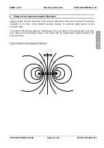
Figure 5 shows the field orientation of the antenna without any influence from metal. The antenna
conductor in the case of the 340x240 antenna consists of conductor paths directly on the
conductor plate.
The range of the antenna depends considerably on the orientation of the transponder in the field.
This antenna has the greatest range in the center with the transponder oriented parallel to the
antenna surface.
Figure 5: Pattern of the magnetic field lines
Label


