IDENTIFICATION
ID LR(M)5400
Installation and mounting
Installation
Page 14 of 30
2.3 Antenna connections
•
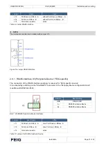
4 x SMA sockets "ANT1
“ to „ANT4"
Input impedance 50 Ω
•
Active external function units (e.g. ID ISC.DAT) can additionally be supplied with 8 V DC via the
antenna connector. The voltage is set via the software.
•
Current consumption
≤ 150 mA.
•
The tightening torque of the SMA socket
≤ 0.45 Nm.
NOTE
•
Standing wave ratio VSWR of the antenna ≤1.3.
•
To achieve optimum reading ranges, the coaxial cables between reader and antenna must have defined lengths. For
all antennas from FEIG ELECTRONIC GmbH and for all antennas which are equipped with the adjustment boards
(e.g. ID DAT, ID MAT-B and ID MAT-S) from FEIG ELECTRONIC GmbH the optimum length of the coaxial cable is
1.35 m (article no. 1654.004.00.00, designation ID ANT.C-B).
See also
“installation instructions” Power Splitter ID ANT.PS-B and ID ANT.MUX.
•
The optimum operating quality of the antenna should be in the range Q = 10...30. To determine the operating quality,
the antenna must be supplied with a 50
Ω source, e.g. a network analyzer or a frequency generator.
•
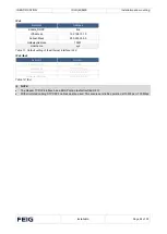
To avoid externally coupled interference, the antenna feed line must be provided with the enclosed EMC toroidal
ferrite Ø 28 mm x 20 mm. For this purpose, the antenna feed line must be passed through the EMC toroidal ferrite at
least four times, tightly wound. The distance between the ANT1-4 reader connection and the toroid should not
exceed 10 cm.
•
When connecting the antenna, make sure that it does not exceed the permissible limits of the national regulations
concerning radio equipment.
Figure 10: Antenna cable with EMV ferrite core


