

-4-
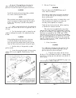
Figure 4.
1.
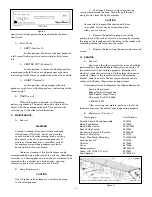
See figure 5. Remove and retain the two
screws which secure the lens. Carefully pull the lens
straight away from the light assembly.
CAUTION
Service life of lamp will be shortened if glass
is touched. If glass has been handled, clean
with a grease solvent.
2.
Remove the defective lamp by carefully
pulling it out of the socket. Install a new lamp by aligning
the pins on the lamp base with the holes in the socket, and
carefully pushing the lamp into the socket.
3.
Replace the lens using the previously removed
screws.
VI. SERVICE.
A.
General.
Servicing, other than cosmetic features, should be
performed by a qualified Federal Signal service center. If
the control unit is not working properly, disconnect all
electrical connections starting with the six-position power
connector. Remove the control unit from the mounting
bracket. Send the unit to the nearest authorized service
center or the Federal Signal service department.
Communication and shipments should be addressed to:
Service Department
Federal Signal Corporation
2645 Federal Signal Drive
University Park, IL 60466
1-800-433-9132
After servicing is complete, perform a test of all
functions to ensure the control unit is operating properly.
B.
Replacement Parts List.
Description
Part Number
Printed Circuit Board Assembly
2001135
Knob, Pushbutton
8573065
Knob, Slide Switch
8536C1041
Bezel, Slide Switch
8573060
Connector, Female, 6-Position
140325-04
Bracket, Mounting
8573070
Screw, Hex Head, Mounting
7011164B-08
Lockwasher, 1/4"
7075078
Chassis
8573068
Cover
8573066
Microprocessor
SM144100
Lamp, G.E. GH-22, 27-watt
8573007
Lens, Amber
8573001-02
simulates the light pattern being executed by the direc-
tional light.
A.
Slide Switch.
1.
LEFT (Position 1).
In this position, the driver side unit produces
a left arrow flashing pattern, instructing traffic to move
left.
2.
CENTER OUT (Position 2).
In this position, a center out flashing pattern
is produced on both the driver and passenger side units,
instructing traffic to move around either side of the vehicle.
3.
RIGHT (Position 3).
In this position, the passenger side unit
produces a right arrow flashing pattern, instructing traffic
to move right.
B.
WARN switch.
When this switch is pressed, an alternating
pattern is produced. The driver side unit activates alter-
nately with the passenger side unit. This pattern will
override any of the slide switch functions.
V.
MAINTENANCE.
A.
General.
WARNING
Crazing (cracking) of lenses will cause reduced
effectiveness of the light. Do not use cleaning
agents (which will cause crazing) such as strong
detergents, solvents, or petroleum products. If
crazing of lenses does occur, reliability of light
for emergency signalling purposes may be re-
duced until lenses are replaced.
Ordinary cleaning of the plastic lenses can be
accomplished by using mild soap and a soft rag. Should fine
scratches or a haze appear on a lens, they can ordinarily be
removed with a non-abrasive, high quality, one-step,
automotive paste cleaner/wax and a soft cloth.
B.
Lamp Replacement.
CAUTION
Use of higher wattage lamps can result in damage
to the colored lenses.
Figure 5.


