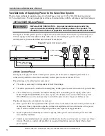
Installation and Maintenance Manual
Model 300VSC-1 and Model 300VSC-1044SB SelecTone Command Units
15
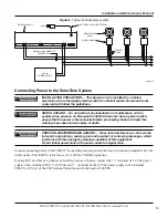
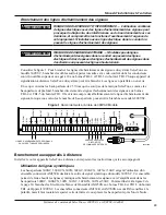
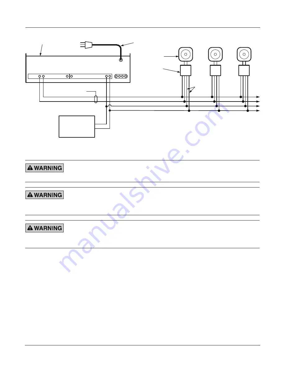
Figure 6 Typical central power system
290A7326
POWER
LINES
MODEL 300GC
24 Vdc
MODEL AM25CK
SIGNAL LINES SHIELDED
TWISTED PAIR
NOT USED WITH MODEL PS600
24 Vdc
POWER SUPPLY
+
+
–
–
5
4
17 1
16
15
TB1
TB2
MODEL 300VSC-1
120 Vac
OUTPUT
Connecting Power to the SelecTone System
INSTALLATION PRECAUTION
—
This device is to be installed by a trained
electrician who is thoroughly familiar with the national electrical code and local
codes and will follow the guidelines.
SHOCK HAZARD
—
Do not perform any installation or maintenance on this
system when power is on. Because the 300VSC does not have a power switch,
ensure that the power is disconnected before proceeding. Failure to heed this
warning may cause serious injury or death.
CROSSTALK/INTERFERENCE HAZARD
—
Cross talk, interference, or hum can be
induced in signal lines, causing poor audio output or confusing messages, which
interferes with the emergency warning capability of this equipment.
Do not install power lines in the same conduit as signal lines.
Connect operating power to the 300VSC by inserting the plug end of the line cord into any standard 120 volt,
60 Hz outlet. The 300VSC is factory-set for 120 Vac 50/60 Hz operation.
If using 24 Vdc either as a primary or auxiliary source of power, connect the “+” terminal of 24 Vdc power
supply to the terminal TB2-15 (+24 Vdc) and “–” terminal of the 24 Vdc power supply to the terminal
TB2-16 (-24 Vdc) of the TB2 terminal block located in the back of 300VSC.
Содержание SelecTone 300VSC-1
Страница 55: ...blank page...


