8
THERMOSTAT
EEC HEATER MODEL
TYPE
5
7.5
10
15
20
SINGLE STAGE
.4
.4
.4
.8
.8
TWO 1ST
N/A
N/A
N/A
.4
.4
STAGE 2ND
N/A
N/A
N/A
.4
.4
Connection to unit
Wire low voltage in accordance with wiring label on the blower.
Use no. 18 AWG wire to make the low voltage connections
between the thermostat, the unit, and the outdoor equipment.
If the thermostat is located more than 100 feet from the unit
use 16 AWG wire. All wiring must be NEC Class 1 and must be
separated from incoming power leads.
The thermostat preheat anticipator should be adjusted to match
the current listed below for the EEC model heat assembly to be
installed.
Transformer Information
The low-voltage transformer is equipped with a 208- or 230-volt
tap. The transformer is factory wired for 230-volt operation. For
208-volt operation, remove the yellow wire from the 230-volt
terminal and install it onto the 208-volt terminal.
The acceptable voltage range for each tap is as follows:
Tap
Voltage Range
230
207 – 253
208
187 – 229
Time Delay Relay Information
A fan relay is provided to control the operation of the indoor
fan motor. All models are equipped with a time delay “OFF”-
type fan relay which will allow the fan motor to continue to
operate for a preset time after the relay is de-energized.
When used with a heat pump, the heat output must be staged
for models above 10 kW. W1 should be wired as auxiliary heat
to assist the heat pump. W2 must only be wired as emergency
heat. Both stages of heat should never be wired so as to be
energized while the heat pump is operating. See the Blower
Speed/Static Table for maximum allowable auxiliary first-stage
heat. All EEC series electric heat assemblies over 10 kW have
breakers factory-installed on the heat assembly.
WARNING
BEFORE PERFORMING ANY WORK ON THIS EQUIPMENT,
POWER SUPPLY MUST BE TURNED OFF AT THE
HOUSEHOLD SERVICE BOX TO AVOID THE POSSIBILITY OF
SHOCK, INJURY, DAMAGE TO EQUIPMENT, OR DEATH.
WARNING
IMPROPER INSTALLATION OF THE ELECTRICAL WIRING
OR THE HEAT ASSEMBLY MAY RESULT IN FIRE, SERIOUS
PERSONAL INJURY, OR DEATH.
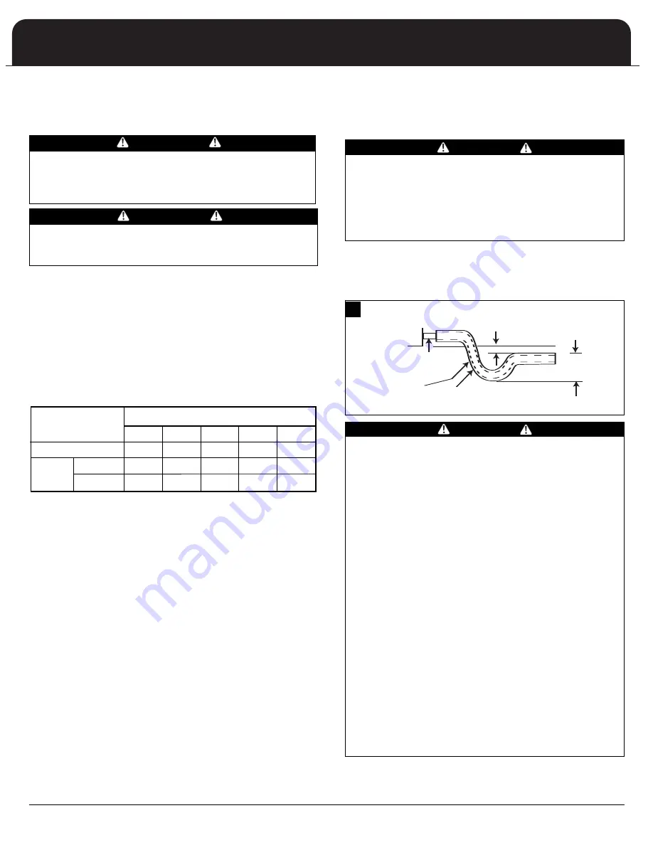
UNIT
FLEXIBLE
TUBING-HOSE
OR PIPE
DRAIN
CONNECTION
A POSITIVE LIQUID
SEAL IS REQUIRED
2” MINIMUM
3” MINIMUM
Install condensate drain trap as close to the coil as possible.
Use drain connection size or larger. Do not operate unit
without trap (see illustration below.) Unit must be level or
slightly inclined toward drain.
CAUTION
1. Do not connect the drain line to a closed sewer.
2. Never terminate an open sewer or drain connection
within the return air duct, platform or return plenum.
3. Pitch the drain line at least
1/4
” per foot away from the
drain pan.
4. If condensate drain connection is on the negative side of
the blower, a trap must be installed to ensure positive
drainage.
5. Condensate drain lines should not be reduced in size
from the connection size supplied.
6. The drain line should be insulated where necessary, to
prevent sweating and damage due to condensate
forming on the outside surface of the line.
7. Test condensate drain line with water before operating
system.
8. If unit is located in or above a living space where
damage may result from condensate overflow, a field
supplied, external condensate pan should be installed
under the entire unit, and a secondary condensate line
(with appropriate trap) should be run from the unit into
the pan. Any condensate in this external condensate
pan should be drained to a noticeable place. As an
alternative to using an external condensate pan, some
localities may allow the running of a separate
3/4
”
condensate line (with appropriate trap) per local code
to a place where the condensate will be noticeable.
CAUTION
For downflow, or any installation where condensate
overflow could create a hazard or water damage, the
emergency drain fitting MUST be used. The emergency
drain MUST be left open. If the emergency drain has to be
piped away from the air handler, its outlet MUST be
installed in a location that would allow any drainage to be
immediately noticed.
Condensate Drain Trap
CONDENSATE DRAIN PLUMBING
24 VOLT CONTROL SYSTEM
11
11


