


42
Motherboard Installation
Installation Precautions
The motherboard contains numerous delicate electronic circuits and components which can become damaged as a result
of electrostatic discharge (ESD). Prior to installation, carefully read the user's manual and follow these procedures:
• Prior to installation, do not remove or break motherboard S/N (Serial Number) sticker or warranty sticker provided by
your dealer. These stickers are required for warranty validation.
• Always remove the AC power by unplugging the power cord from the power outlet before installing or removing the
motherboard or other hardware components.
• When connecting hardware components to the internal connectors on the motherboard, make sure they are
connected tightly and securely.
• When handling the motherboard, avoid touching any metal leads or connectors.
• It is best to wear an electrostatic discharge (ESD) wrist strap when handling electronic components such as a
motherboard, CPU or memory. If you do not have an ESD wrist strap, keep your hands dry and first touch a metal
object to eliminate static electricity.
• Prior to installing the motherboard, please have it on top of an antistatic pad or within an electrostatic shielding
container.
• Before unplugging the power supply cable from the motherboard, make sure the power supply has been turned off.
• Before turning on the power, make sure the power supply voltage has been set according to the local voltage
standard.
• Before using the product, please verify that all cables and power connectors of your hardware components are
connected.
• To prevent damage to the motherboard, do not allow screws to come in contact with the motherboard circuit or its
components.
• Make sure there are no leftover screws or metal components placed on the motherboard or within the computer
casing.
• Do not place the computer system on an uneven surface.
• Do not place the computer system in a high-temperature environment.
• Turning on the computer power during the installation process can lead to damage to system components as well as
physical harm to the user.
• If you are uncertain about any installation steps or have a problem related to the use of the product, please consult a
certified computer technician.
Содержание PP-9635
Страница 1: ...Service Manual Model PP 9635 Last Modified 2017 1 13...
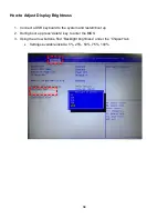
Страница 9: ...8 Physical Dimension Display Tilt Angle 70 90...
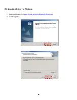
Страница 17: ...16 Realtek LAN Driver 1 Download drivers from www fecpos com en global ams Download 2 run Steup exe...
Страница 26: ...25 Advanced...
Страница 40: ...39 Motherboard Specifications...
Страница 41: ...40...
Страница 42: ...41...
Страница 44: ...43 Motherboard Specification...
Страница 45: ...44...
Страница 46: ...45 Motherboard Connectors Internal Connectors...
Страница 47: ...46...
Страница 48: ...47...
Страница 49: ...48...
Страница 50: ...49...
Страница 51: ...50...
Страница 52: ...51...
Страница 53: ...52...
Страница 54: ...53...
Страница 55: ...54...
Страница 56: ...55...
Страница 57: ...56...
Страница 58: ...57...
Страница 59: ...58...
Страница 60: ...59...
Страница 61: ...60...
Страница 62: ...61 BIOS...
Страница 63: ...62 Main...
Страница 66: ...65 Advanced ACPI Settings Advanced IT8786E Super IO Configuration...
Страница 67: ...66...
Страница 68: ...67...
Страница 69: ...68 Advanced Hardware Monitor Advanced S5 RTC Setting...
Страница 70: ...69 Advanced CPU Configuration...
Страница 71: ...70 Advanced SATA Configuration Advanced CSM Configuration...
Страница 72: ...71 Chipset Menu...
Страница 73: ...72 Wake on LAN default is Enabled Wake on Ring default is Disabled...
Страница 76: ...75 Security Secure Boot...
Страница 77: ...76 Security Key Management...
Страница 78: ...77...
Страница 79: ...78 Boot Menu...
Страница 80: ...79 Save Exit Menu...
Страница 104: ...103 PK6 RD9000PH1869 Silica Gel 2 PK7 RC9000PM1371 Ziplock bags 1 PK8 RC9000PM2318 Protection Mylar film for Monitor 1...
Страница 116: ...115 PK7 RC9000PM1371 Ziplock bags 1 PK8 RC9000PM2318 Protection Mylar film for Monitor 1...