FEC Remote Lighting Controller V4 HP0832
User Installation and Operation Manual
© Interleader Ltd 2020
46 of 64
26/08/2020
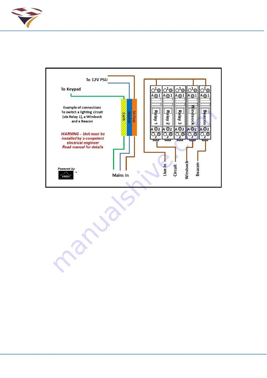
9.10 Basic Wiring Diagram
A simplified circuit diagram is shown below for a single switched circuit.
NB
– To allow the lights to be operated in the event of a unit failure it is strongly recommended
that a mains by-pass switch is incorporated into the circuit by a qualified electrician.
Notes
1) The 5A fuse in the DIN rail holder is for fusing the feed to the 12V PSU only.
2) Installers can add additional DIN rail mounting Live, Neutral and Earth terminals.
3) DIN Rail mounting fuse holders may also be added.
4) If additional items are added to the rail, follow the instructions below.
5) Secondary circuit load characteristics may require an external contactor.
NB
– Do not run the light circuits via the 5A fuse – this is only for the
feed of the 12V mains Power Supply Unit (PSU).
Any light circuit fuses should be specific to each circuit.
DIN Rail Mounted Items
DIN rail mounting terminals etc. generally ‘snap’ onto the rail with plastic clips either side.
The Earth terminal has grips onto the rail which are metal, connected to the terminal block (to
earth the rail) and actuated by the middle screw (of three).
To add terminal blocks:
a) Slacken the middle screw of the earth block and slide it down the rail (there is no need to
remove it)
b) Snap in the required additional terminals (sliding others as required)
c) Push the earth terminal back up to ensure no gaps between terminal and re-tighten the
middle screw
NB
– Ensure that no live connections are exposed by the insertion of additional
connectors.
Содержание HP0832
Страница 64: ...End of Document...


