Σ
YG-S7G2-43C-MDK User’s
Manual
11/18/2015
Copyright ©2015,
Future Designs, Inc
Page
3
of
28
Table of Contents
Important Legal Information
.........................................................................................................................................
2
Σ
yG-S7G2 Modular Development Kit (MDK) Overview
................................................................................
5
1.1
Introduction
...................................................................................................................................................
5
1.2
ESD Warning
................................................................................................................................................
5
1.3
Renesas Synergy S7G2 Microcontoller Block Diagram
...............................................................................
6
1.4
Σ
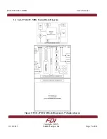
yG-S7G2-43C-MDK System Block Diagram
............................................................................................
7
1.5
Requirements
.................................................................................................................................................
8
1.6
Σ
yG-S7G2 SOM Power Requirements
.........................................................................................................
8
Getting Started
..................................................................................................................................................
8
2.1
Setting up the Hardware
................................................................................................................................
8
2.2
Demonstration Software
..............................................................................................................................
10
Σ
yG-S7G2 SOM System on Module Board Components
..............................................................................
12
3.1
ARM Mini-JTAG J2
...................................................................................................................................
12
3.2
Tag Connect J7
............................................................................................................................................
13
3.3
MicroSD Socket J1
......................................................................................................................................
14
3.3.1
Inserting the microSD card into the microSD socket
..........................................................................
15
3.3.2
Removing the microSD card from the microSD socket
......................................................................
16
3.4
Ethernet PHY U5
........................................................................................................................................
16
3.5
200-pin SOMDIMM Connector Details J4
.................................................................................................
17
Carrier Board Components
..............................................................................................................................
21
4.1
DC Power Input
...........................................................................................................................................
21
4.2
Alternate Power Input
.................................................................................................................................
21
4.3
USB Power Device
......................................................................................................................................
21
4.4
USB Power Host
.........................................................................................................................................
22
4.5
Ethernet
.......................................................................................................................................................
22
4.6
CAN/RS485
................................................................................................................................................
23
4.7
RS232
..........................................................................................................................................................
24
4.8
External I2C
................................................................................................................................................
24


