FCI MT86 Скачать руководство пользователя страница 27

MT86/MT86HT Flow Meter 

TROUBLESHOOTING 

Fluid Components International LLC 

23 


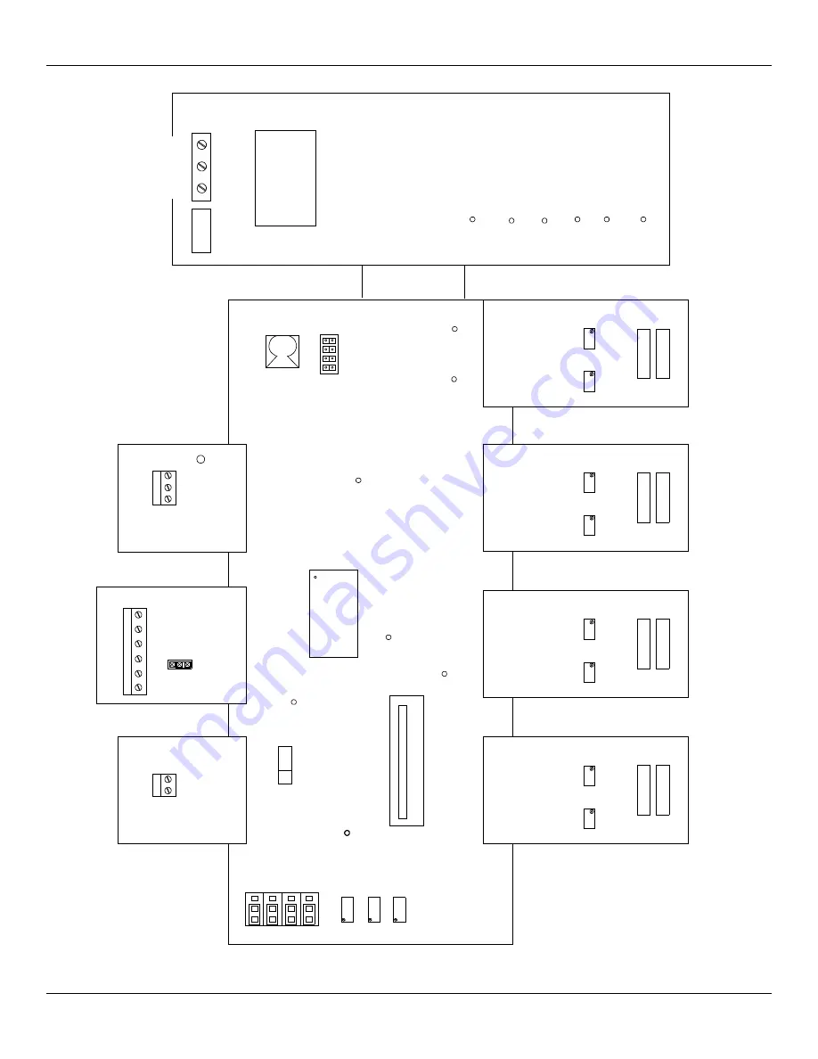
Figure 11 – Electrical Assembly Layout 

C00129-1

F

U

S

E

AC GND

AC NEUT

AC LINE

TRANS-

FORMER

TP2

TP3

TP4

TP5

TP6

TP1

ASS Y 011528-XX (SHOWN)

(FOR 24VDC USE ASS Y 012059-XX) (NOT SHOWN)

+15V

+5V

GND

-5V

-15V

+28V

VOLTS DC  ± 0.5V

POWER SUPP LY BD.

2

D

A

E

H

H

E

A

D
1

D

R

A

O

B

R18

R17

T

U

P

N

I

ASS Y 0011515-XX

H

E

A

D

4

3

D

A

E

H

ASS Y 0011515-XX

I

N

P

U

T

R17

R18

B

O

A

R

D

H

E

A

D

5

6

D

A

E

H

D

R

A

O

B

R18

R17

T

U

P

N

I

ASS Y 0011515-XX

H

E

A

D

8

7

D

A

E

H

ASS Y 0011515-XX

I

N

P

U

T

R17

R18

B

O

A

R

D

TP16

SIG GND

TP15

+10V

O

P

E

N

1 (-) RST

2

3 (-) MAN

4 (-) TC

HEAD

SELECT

SW2

ASS Y 0011552-XX

+

P2

-

ASS Y 011563-XX

OP

SW4

0 -10 V

OUTPUT

CAL

TP13

MT86 CONTRO L BD.

TP9

INHI

INLO

TP10

P12

U14

EPROM

DIG

TP4

GND

P2

CR1

ASS Y 012576-XX

NC

POLE

NO

R

E

M

O

T

E

A

NC

A

POLE

A

NO

B

NC

B

POLE

B

NO

ASS Y 011581-XX

J2

J1

S

W

I

T

C

H

P

O

I

N

T

B

O

A

R

D

m

A

/

V

O

L

T

O

U

T

P

U

T

J8 J6 J4

J2

GND

TP5

SIG

R23

R17

R16

J1

J3

J5

J7

CAL ZERO SPAN

Содержание MT86

Страница 1: ...Doc No 003162 Rev G...

Страница 2: ...onal LLC FCI Disclosure of this data to you is expressly conditioned upon your assent that its use is limited to use within your company only and does not include manufacture or processing uses Any ot...

Страница 3: ...Zero Based Calibration 10 Delta R Table 11 Generating New Delta R Tables 11 New Calibration Procedure in field 12 4 MAINTENANCE 17 Introduction 17 Maintenance 17 5 TROUBLESHOOTING 19 Quick Check Troub...

Страница 4: ...Output Module 8 Figure 6 Battery Jumper and Reset Locations 9 Figure 7 Zero Based Calibration 11 Figure 8 Zero and Span Adjustment 14 Figure 9 A D Data Sheet 15 Figure 10 Terminal Plug 21 Figure 11 E...

Страница 5: ...s of thermowells metal tubes of the same size and shape Each pair of thermowells is welded together One thermowell pair has a heating element placed in one tube and an active Resistance Thermal Detect...

Страница 6: ...n 100 feet maximum Longer distances are possible using a heavier gauge wire for the heater circuit See Table 1 page 6 for more information Turn down ratio 2 1 to 100 1 within flow element range custom...

Страница 7: ...cations Never weld to process connection or a structural support Damage resulting from moisture penetration of the local or remote enclosure is not covered by product warranty The flow transmitter con...

Страница 8: ...losure This flat surface is known as the Reference Flat and includes a flow arrow etched on its surface to indicate flow direction See Figure 2 for details Figure 2 Flow Element Showing Flat Area Flan...

Страница 9: ...nds installing an AC or DC power disconnect switch and fuse near the flow transmitter to interrupt power during installation maintenance calibration and troubleshooting procedures Remote Hardware APPE...

Страница 10: ...ement wiring to the input boards Run separate excitation and sense wires for the Active Reference and Ground connections The flow meter will not operate properly without these connections If the Activ...

Страница 11: ...A C LINE D C D C GND CHASSIS OPTIONA L 24 VDC INPUT TS8 TS7 TS6 TS5 TS4 TS3 TS2 TS1 CONN NO 4 8 7 6 5 HEAD NO 3 2 1 BOARD CONTRO L mA VO LTAGE OUTPUT BD OUTPUT BD mA VO LTAGE IN OUT ISOLATOR 1 OUT IS...

Страница 12: ...e has its own set of output terminals which provide an isolated 4 to 20mA output equal to the non isolated instrument output This one to one current isolation is used to prevent instrumentation ground...

Страница 13: ...f power There is a jumper on the back of the totalizer and display board that needs to be repositioned to the ON position See Figure 6 for the jumper location The estimated life of the battery is 3 ye...

Страница 14: ...mass flow The output signal shows only the flow rates between the upper and lower limits of the calibrated range For zero based instruments the output signal will show zero whenever the flow rate is b...

Страница 15: ...he coefficients except in special circumstances as the overall accuracy of the system is tied to these numbers Call Customer Service if there is a problem in this area The Calibration Table is a print...

Страница 16: ...or to Read Volts and repeat Steps 10 through 16 Remember to set the head select switch SW2 to the number 2 position for sensing point number 2 20 Repeat this procedure for all the remaining sensing po...

Страница 17: ...needed is the true flow rate and the indicating milliamp output of the flow meter Record and have the information available for FCI to review The procedure is basically the same as the span adjustment...

Страница 18: ...n the Delta R table one column is categorized as Voltage In Non Linear TP9 to TP10 Use the following equation to calculate the A D number for the Non Temperature Compensated flow meter only Write down...

Страница 19: ...MT86 MT86HT Flow Meter OPERATION Fluid Components International LLC 15 Figure 9 A D Data Sheet...

Страница 20: ...OPERATION MT86 MT86HT Flow Meter 16 Fluid Components International LLC This Page Intentionally Left Blank...

Страница 21: ...verify the calibration of the flow meter and re calibrate if necessary contact the factory Electrical Connections Periodically inspect the cable connections the terminal strips and the terminal block...

Страница 22: ...MAINTENANCE MT86 MT86HT Flow Meter 18 Fluid Components International LLC This Page Intentionally Left Blank...

Страница 23: ...ng Equipment 2 each digital multimeter DMM capable of measuring ohms milliamps and AC or DC voltage with a 4 1 2 digit resolution 3 each precision decade resistance boxes however they are optional if...

Страница 24: ...e null and gain potentiometers have been sealed If they are sealed the flow meter is setup to use temperature compensation If they are not then no temperature compensation is used An open switch is th...

Страница 25: ...gher temperatures at the sensing points Resistance values will vary with temperature Figure 10 Terminal Plug Table 4 Terminal Plug Resistances Pin Number Approximate Resistance MT86 MT86HT Approximate...

Страница 26: ...power supply terminal block TS1 to be sure the correct power is applied Check the power supply voltages using the test points provided See Table 5 and Figure 11 for the proper operating voltages If th...

Страница 27: ...H ASS Y 0011515 XX I N P U T R17 R18 B O A R D H E A D 5 6 D A E H D R A O B R18 R17 T U P N I ASS Y 0011515 XX H E A D 8 7 D A E H ASS Y 0011515 XX I N P U T R17 R18 B O A R D TP16 SIG GND TP15 10V O...

Страница 28: ...TROUBLESHOOTING MT86 MT86HT Flow Meter 24 Fluid Components International LLC Figure 12 Control Board Layout...

Страница 29: ...are at 80 F 27 C and 14 7 PSIA and at no flow The readings will vary with temperature and flow However the reference voltages should always match and the active voltages should always match The active...

Страница 30: ...to the verification with a field calibrator procedure 1 Turn OFF the power to the instrument Disconnect the flow element cable from the input board terminal block TS1 2 Connect two decade boxes or on...

Страница 31: ...hen the Delta R Data for the output modules and displays will not match the values recorded on the Delta R data sheet See the jumper listing in Table 2 to determine if the span and zero activation cir...

Страница 32: ...bles the head select switch SW2 to select and monitor one sensing point Select the sensing point to be tested with the head select switch SW2 6 With the FC81 field calibrator function switch in the ou...

Страница 33: ...Use this test signal to sweep through the full signal range 0 10 VDC and observe operation of the output modules and customer interface circuitry 1 Place switch SW4 in the CAL CALibrate position 2 Con...

Страница 34: ...are no field repairable items at the component level other than fuses Note Any unauthorized repairs that are done at the component level will void the warranty Contact the authorized FCI field represe...

Страница 35: ...1000 Ohm Flow Meters Control Board Adjust Pot 100 Ohm 1000 Ohm R8 4 99K 1 21 5K 1 Gain 20X 10X Input Board Adjust Pot 100 Ohm 1000 Ohm R1 R7 6 65K Not Used RN3 1K 10K Jumpers Installed Input Board Ad...

Страница 36: ...by looking at the Order Information Sheet that was filled out at the time the flow meter was ordered Table 11 Recommended Spare Parts Quantity Description 1 Power supply board P N 011528 XX or 012059...

Страница 37: ...t to FCI freight prepaid for disposition Customer Service 1 In the event of problems or inquiries regarding the flow meter please contact the Regional or Country Authorized FCI Field Agent There is an...

Страница 38: ...TROUBLESHOOTING MT86 MT86HT Flow Meter 34 Fluid Components International LLC This Page Intentionally Left Blank...

Страница 39: ...4X 31 DISPLAY AND TOTALIZER 3RD PORT PROVIDED WITH 6 AND 8 POINT SYSTEMS 6 12 11 00 12 50 17 87 305 454 425 38 1 318 379 92 3 57 2 279 155 C00319 1 1 79 SHOWN WITH OPTIONAL RATE SHOWN WITH OPTIONA L R...

Страница 40: ...APPENDIX A DRAWINGS MT86 MT86HT Flow Meter 36 Fluid Components International LLC C01156 1 1...

Страница 41: ...CH NPT 1 2 13UNC 2B HORIZON TAL FLOW APPLIC ATIONS VERTICA L FLOW APPLIC ATIONS APPLIC ATIONS HORIZON TAL 1 2X FLOW X APPLIC ATIONS FLOW VERTICA L 25 1 2 13UNC 2B 1 00 1 00 U LENGTH 2 06 MAX 3 35 U LE...

Страница 42: ...APPENDIX A DRAWINGS MT86 MT86HT Flow Meter 38 Fluid Components International LLC This Page Intentionally Left Blank...

Страница 43: ...ignal Heater HTR The flow element part that heats the active RTD Local Enclosure The enclosure attached to the flow element usually contains the wiring terminal block Reference Flat A flat part on the...

Страница 44: ...APPENDIX B GLOSSARY MT86 MT86HT Flow Meter 40 Fluid Components International LLC This Page Intentionally Left Blank...

Страница 45: ...upport outside the contiguous United States Alaska or Hawaii contact your country s FCI International Representative or the one nearest to you After Hours Support For product information visit FCI at...

Страница 46: ...call the technician completes a formal detailed service report The formal report is mailed to the customer after the technician s return to the factory or office Field Service Rates All field service...

Страница 47: ...MT86 MT86HT Flow Meter APPENDIX C CUSTOMER SERVICE Fluid Components International LLC 43...

Страница 48: ...APPENDIX C CUSTOMER SERVICE MT86 MT86HT Flow Meter 44 Fluid Components International LLC...

Страница 49: ...itability for the purpose for which they are intended or used Should the Buyer receive defective goods as defined by this paragraph the Buyer shall notify the Seller immediately stating full particula...

Страница 50: ...APPENDIX C CUSTOMER SERVICE MT86 MT86HT Flow Meter 46 Fluid Components International LLC This Page Intentionally Left Blank...

Страница 51: ...lected for input power of 24 VDC Since the manufacturer does not supply the power source or transformer for these connections the responsibility for the conditioning of these sources and associated co...

Страница 52: ...t A resides at Fluid Components Intl European Service Center Beatrix De Rijkweg 8 5657 Eg Einhoven Netherlands Phone 31 40 2 571 972 FAX 31 40 2 517 809 Manufacturer Location The technical documentati...

Страница 53: ...MT86 MT86HT Flow Meter APPENDIX D CE CONFORMANCE Fluid Components International LLC 49 This Page Intentionally Left Blank...

Страница 54: ...MT86 MT86HT Flow Meter Fluid Components International LLC 003162 Rev G...

Отзывы: