


FS10 Series
OPERATION
Fluid Components International LLC
23
3. OPERATION
General
Before applying power to the instrument, it is recommended that a third party inspect the installation workmanship. Make sure wires are not pinched
or frayed. Check for matching serial numbers on the sensing element and the control circuit. Verify that the power and alarm circuits are properly
connected. Review the instrument configuration and its application.
Units supplied with LEDs will have at least one LED on or slowly blinking to indicate power on. Apply power and look for the power indicator light.
After power is established let the instrument warm up for 5 minutes. Refer to the set-up information in the sections below. Properly connect the
switch to earth ground to ensure safe and problem-free operation.
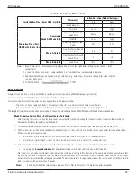
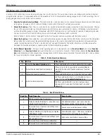
FS10 Function Overview
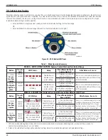
The FS10 flow monitor comes configured for use as a flow or temperature meter. The output of the switch configuration is an SPDT relay
contact or open collector to ground [N-channel MOSFET] output (sync). A 4-20 mA output signal is also active as a signal reference. In the
transmitter configuration, either flow or temperature is assigned to the 4-20 mA output. The table below shows the possible output configura-
tions, including the status of the LED bar display.
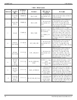
Table 2 – Output Configuration [Field Selectable with PC Interface Kit]
Configuration
4-20 mA Output
Relay On/Off Output
LEDs
1 (default)
Corresponds to flow
measurement
Controls relay switch on/off from flow
Reflects flow. Flashing LED indi-
cates Relay Limit.
2
1
Corresponds to flow
measurement
Frequency corresponds to flow
Reflects flow. No Relay Limit
indication.
3
1
Corresponds to flow
measurement
Frequency corresponds to temperature
Reflects flow. No Relay Limit
indication.
4
Corresponds to temp
measurement
Controls relay switch on/off from flow
Reflects temperature. No Relay
Limit indication.
5
Corresponds to temp
measurement
Controls relay switch on/off from flow
Reflects flow. Flashing LED indi-
cates Relay Limit.
6
1
Corresponds to temp
measurement
Frequency corresponds to flow
Reflects temperature. No Relay
Limit indication.
Note: 1.
Caution
: Frequency output function must only be used with solid state output. Relay must NOT be engaged. Select proper jumper
setting for MOSFET solid state output (see Section 3, Instrument Wiring).
• Flow measurement is mapped using CUST_FLOW_MIN and CUST_FLOW_MAX in the 4-20 mA output configuration.
• Temperature measurement is mapped using CUST_TEMP_MIN and CUST_TEMP_MAX in the output configuration and reflected in the
4-20 mA output when configuration 4 or 5 is selected. The default temperature range mapped to the 4-20 mA output is 0 °F to 250 °F
[-17.8 °C to 121 °C]. Use the FS10 Windows PC interface program to rescale the temperature output as required.
The output configuration setting is normally factory set but it can be changed in the field if required. Use caution when making any configura-
tion changes, as the monitor may not have been properly calibrated to accommodate the new setting. Use the Windows PC interface or the
RS232 interface to make a change in output configuration.
Note
:
ATEX-approved units are supplied with a polycarbonate UV filter under the silicone boot. Remove the boot and filter to use
button setup (see next section).
Содержание FS10A
Страница 26: ...INSTALLATION FS10 Series 22 Fluid Components International LLC This Page Intentionally Left Blank...
Страница 54: ...OPERATION FS10 Series 50 Fluid Components International LLC This Page Intentionally Left Blank...
Страница 60: ...APPENDIX A APPROVALS FS10 Series 56 Fluid Components International LLC This Page Intentionally Left Blank...
Страница 62: ...APPENDIX A APPROVALS FS10 Series 58 Fluid Components International LLC This Page Intentionally Left Blank...
Страница 75: ...FS10 Series APPENDIX C CUSTOMER SERVICE Fluid Components International LLC 71...