Page
6
/
37
Detection Sub-assembly / Electronic Enclosure
The detection sub-assembly is housed in a flame-proof box which permits the use of the
flowmeter in electrically classified areas (UL/cUL Class 1 Div 1 Group C & D; ATEX/IECEx II1G – IIC
T6). The electronic enclosure integrates the following elements:
•
A pick up coil housed in the bottom of each boss and kept in position by means of a ring
•
A coil/pre-amplifier connection cable
•
An optional pre-amplifier which allows operators to significantly increase the maximum
distance between the flowmeter and the electronic display and/or flow computer (up to
5,000 meters/16,000 ft)
Flow Conditioning
According to API MPMS Chapter 5.3 and ISO 2715, “The performance of turbine meters is
affected by swirl and non-uniform velocity profiles that are induced by upstream and downstream
piping configurations, valves, strainers, pumps, fittings, joint misalignment, protruding gaskets,
welding projections, or other obstructions. Flow conditioning shall be used to overcome the
adverse effects of swirl and non-uniform velocity profiles on turbine meter performance.”
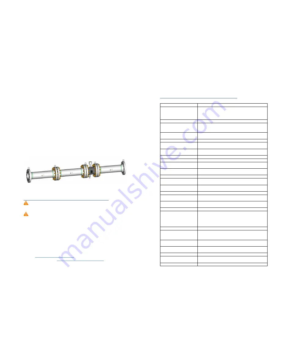
Faure Herman can supply the flow conditioning assembly which integrates upstream piping,
flow conditioning element (plate, straightening vanes, etc.) and downstream piping (to be utilized
at time of meter calibration).
Figure 4. Complete Meter run with upstream/downstream spool pieces and flow conditioner
Chapter 3: Equipment Receipt, Storage and Handling
Upon receipt of the TZN turbine meter, inspect the packing case for any shipping damage. The
meter must be carefully removed from the packing case and inspected for potential damage or
missing parts (including documentation)
Before installation, the unit should remain stored in its original packing, protected against
adverse weather conditions, and maintained at temperatures between -20 /+70 °C (-4 /+158 °F).
If the meter isn’t installed within a month, FH recommends maintaining the metering assembly
in an inerted atmosphere (nitrogen) or fluid filled state (light hydrocarbons). Please check
applicable regulation to ensure that all calibration requirements have been met.
Prior to installing the TZN, visually inspect the turbine meter; pay particular attention to name
plate (check for serial number, process conditions, direction of flow …), flange rating and general
conditions.
Should the product be damaged or documents missing, please contact the Faure Herman
Worldwide Customer Support & Service via phone, email or website:
Hotlines:
+1 (713) 597 4827 (North America)
+33 (0)2 43 60 28 55
Email:
Online Assistance website:
https://faureherman.zendesk.com/hc/en-us
Page
35
/
37
Risk analysis according to Directive 2014/68/EU
Suitable resistance
Requirements
Excess temperature and
pressure
Temperatures and pressure limits should be considered during
the design phase.
The limitations are indicated on the equipment; the user is
responsible to set up equipment properly.
Wind / Snow influence
NA: Without influence considering the small surface areas
Earthquake
The equipment is not intended for use in a seismic zone. If
operated as such, it is the responsibility of the user to provide
adapted devices.
Support, binding and piping
reaction
The equipment is designed to be joined to other piping; it
does not have its own supports.
Thermal fatigue
Design choice of materials follows ASME B31.3.
Mechanical fatigue
This is metrological equipment; it is the user’s responsibility to
install properly to avoid mechanical stress.
Vibration
This is metrological equipment; it is the user’s responsibility to
install away from sources of vibration.
Handling and operation
Comments
Closing and opening
NA: the equipment does not have an aperture or closure.
Dangerous emissions from
valves
NA: the equipment does not have a valve.
Access to the inside
NA: the equipment does not have access (inspection hatch,
manhole).
Surface temperature
The user is responsible for indication of hot surfaces.
Decomposition of unstable fluid
NA: The equipment is used for the transfer of fluid not
storage.
Handling
Equipment > 30kg is equipped with lifting rings for safe
handling.
Draining and venting
Comments
Pressure wave
This is sensitive metrological equipment; it is the user’s
responsibility to install properly to avoid pressure waves.
Vacuum collapse
Minimal service pressure of 0 bar.g indicated on the plate.
This equipment is not designed to work under vacuum.
Corrosion and chemical attack
Comments
Uniformly generalized
Consideration of corrosion thickness.
Choose proper materials and application of painting systems
adapted to the environment.
It remains under user responsibility to periodically check the
condition of its installation.
Selective
Choose proper materials
Galvanic
Choose proper materials and review compatibility of
materials. It is the user’s responsibility to set up adapted
devices, grounding straps, cathodic protection…
By differential aeration
Choose proper materials – Maintain the equipment full of
fluid.
By puncture, crevice,
intergranular
Choose proper materials. Review compliance with NACE
MR0175 requirements if applicable.
Ammonia
Choose proper materials
Under stress
Choose proper materials. Review compliance with NACE
MR0175 requirements if applicable.
Wear
Comments


