


20
Functional Description
4
Motor without attachment
4.1
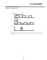
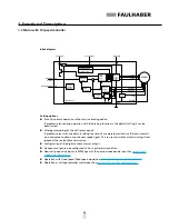
4.1.1 Connection functions
The servomotor requires and external control for operations and has the connection options listed in
section 3
.
Phase C to Phase A (core 1 – 3)
The rotating field required to operate the motor is applied to phases C to A.
Voltage range: 0 V AC to U
max
.
The following limits must be adhered to for U
max
:
Note and observe limit speed (see
section 7 "Technical Data"
).
U
max
< 50 V AC (below the Low Voltage Directive).
CAUTION!
Harmonic components
When the servomotor is operated with block commutation or PWM, harmonic components can arise,
as a result of which the emission behaviour of the motor can worsen.
Ensured operation of the motor within the EMC requires a harmonic-free rotating field, or the
f
suggested FAULHABER control (see
section 3.4 "Connection Examples"
).
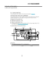
GND (core 4)
Joint ground of the hall sensors.
U
DD
(core 5)
Joint power supply of the hall sensors.
Voltage range: 2.2 … 18 V DC.
Input current: < 18 mA.
Output signals Hall sensor C to Hall sensor A (core 6 – 8)
Signal output of the Hall sensors.
Voltage range: 0.1 V DC … U
DD
.
Output current: < 25 mA.
The output current results from the applied pull-up voltage and the pull-up resistance used.
Signal setup: The Hall signals are 120° out of phase with each other according to the phases. Due to
the 4-pole version, the switching frequency is twice as high as the speed.
Содержание 2232***BX4 series
Страница 1: ...EN Brushless DC servo motors Series 2232 BX4 S Series 2250 BX4 S Instruction Manual WE CREATE MOTION ...
Страница 2: ......
Страница 58: ...58 Notes ...
Страница 59: ...59 Notes ...