


9WMV/V + Series User’s Manual
2-5
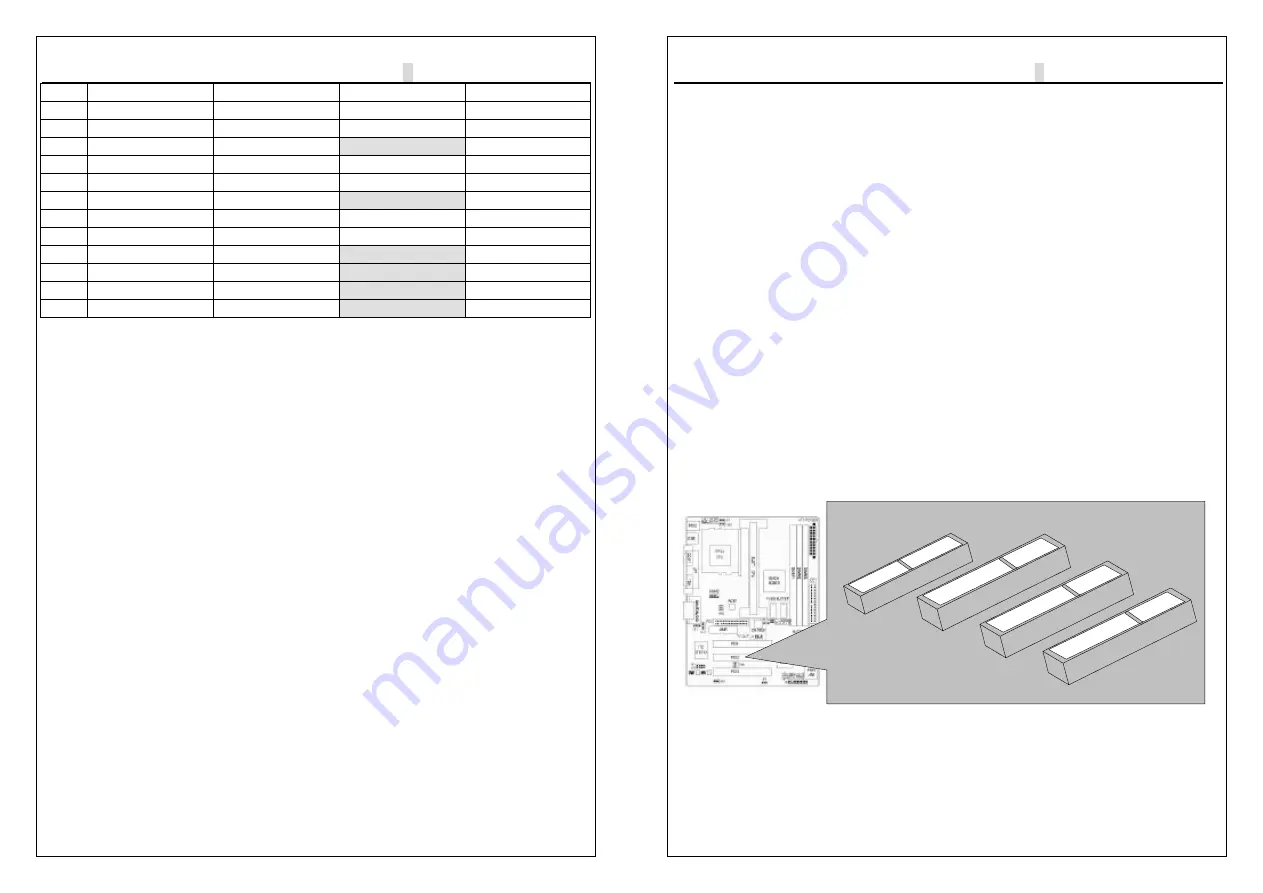
ITEM
DIMM 1
DIMM 2
DIMM 3
TOTAL SIZE
1
32MB-Single
32MB-Single
32MB-Single
96MB
2
32MB-Double
32MB-Single
32MB-Single
96MB
3
32MB-Double
32MB-Double
Don’t use
96MB
4
64MB-Single
64MB-Single
64MB-Single
192MB
5
64MB-Double
64MB-Single
64MB-Single
192MB
6
64MB-Double
64MB-Double
Don’t use
128MB
7
128MB-Single
128MB-Single
128MB-Single
384MB
8
128MB-Double
128MB-Single
128MB-Single
384MB
9
128MB-Double
128MB-Double
Don’t use
256MB
10 256MB-Single
256MB-Single
Don’t use
512MB
11 256MB-Double
256MB-Single
Don’t use
512MB
12 256MB-Double
256MB-Double
Don’t use
512MB
2-3 Central Processing Unit (CPU)
The Motherboard provides a ZIF Socket 370 and a SLOT 1. The CPU that came
with the motherboard should have a fan attached to it to prevent overheating. If
this in not the case, then purchase a fan before you turn on your system. Be sure
that there is sufficient air circulation across the processor heat sink, or the
processor could overheat and damage both the processor and the motherboard.
To install a CPU, first turn off your system and remove its cover. Locate the ZIF
socket and open it by first pulling the lever sideways away from the socket then
upwards to a 90-degree angle. Insert the CPU with the correct orientation as
shown. The notched corner should point towards the end of the lever. Because
the CPU has a corner pin for two of the four corners, the CPU will only be fitted in
the orientation as shown. The picture is for reference only: you should have a
CPU fan that covers the top side of the CPU. With the added weight of the CPU
fan, no force is required to insert the CPU. Once completely inserted, close the
socket lever while holding down the CPU.
9WMV/V + Series User’s Manual
2-6
2-4 Expansion Cards
Always unplug the power supply when adding or removing expansion cards or
other system components. Failure to do so may cause severe damage to both
your motherboard and expansion cards.
Expansion Card Installation Procedure The Motherboard has 3 PCI and 1 AMR
expansion slots. You may install up to 3 PCI cards and 1 AMR card on this
motherboard. To install the PCI cards or AMR card, please follow the following
procedure:
1. Read the documentation for your expansion card and make any necessary
hardware or software settings for you expansion card, such as jumpers or
switches.
2. Remove your computer system cover and the bracket plate with screw on the
slot you intend to use. Keep the bracket for possible future use.
3.Carefully align the card connectors and press firmly.
4.Secure the card on the slot with the screw you removed above.
5.Replace the computer system cover.
6.Setup the BIOS if necessary.
7.Install the necessary software drivers for your expansion card.
Note: To install the AMR Card. You should set the “AC97 Modem” as ”auto” in the
”INTEGRATED PERIPHERALS” of the BIOS Setup.
SLOT Area
AMR
PCI


