

Page 2 of 4
www.fast-stat.com
1.
Measure the transformer voltage to check if it drops
below 23V while in use. The Model 5000 may not
function properly outside of the 23-28 volt range and
the transformer may need to be replaced.
2. If applying 24V to ‘G’ on the Sender activates ‘W1’
on the Receiver, or vice versa, then the two wires
that connect the Sender and Receiver are crossed.
Disconnect the thermostat cable and swap the
connections.
3. At the thermostat, jumper ‘R’ to ‘G’ to activate the
fan. Jumper ‘R’, ‘G’, and ‘Y’ to activate the fan and
condenser. Jumper ‘R’ to ‘W1’ to activate first stage
heat. Jumper ‘R’, ‘W1’, and ‘W2’ to activate second
stage heat. If all functions work correctly when
jumpered, then the thermostat may not be configured
properly. If no functions operate there may be a break
in the thermostat cable.
4. If the Receiver is set to the highest voltage possible
and still does not activate the equipment when called,
then the power consumption of the thermostat is too
low. This can be fixed by adding a resistor in parallel
to the thermostat. See ‘Low Power Thermostats’ for
more information.
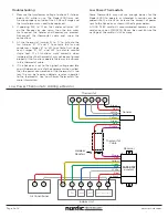
Some thermostats may not use enough power for the
Model 5000 to operate as intended. A resistor can be
added into the circuit to increase the amount of power
sent to the Receiver, as shown in the diagram below.
A 1000
Ω
, 1W resistor is recommended, however similar
resistance values (750-1500
Ω
) can be used. Ensure the
wattage of the resistor is 1W or more.
Troubleshooting
Low Power Thermostats
Low Power Thermostats: Adding a Resistor
Air Conditioner
C
Y
Sender
Yellow
Green
Red
Purple
Blue
Blue
White
Green
Yellow
Red
Black
Red
Purple
White
Red
Black
Thermostat
Cable
R
C
G
Y
Thermostat
W1
W2
Model 5000
FAST-STAT
Receiver
Indoor Unit
W1
Heat 1
W2
Heat 2
24V Transformer
G
Fan
Y
R
C
Added
Resistor