Farris Engineering 2700 Series Скачать руководство пользователя страница 9

9

Seat Leakage Test

1. After the set pressure test, perform the seat leakage

test. With the valve mounted on the test stand, 
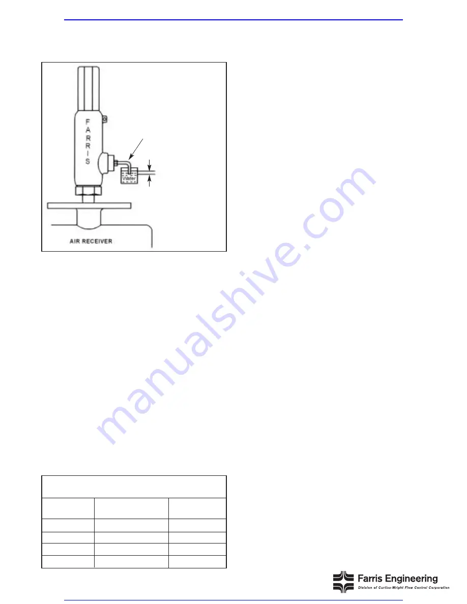
attach a blind test fixture as shown in Figure 1.8 
(air, gas & vapor service valves only). For steam 
and water seat leakage testing, see #4-5.

2. For metal and soft seated valves, the pressure is 

held at 90% of cold differential test pressure 
(CDTP) when CDTP is greater than 50 psig. For 
CDTP of 50 psig and below, the pressure should be
held 5 psig below CDTP.

3. Bring the pressure up and hold it for one minute for 

valves up to 2” inlet size, two minutes for valves 
from 2 1/2”-4” inlet size, and five minutes for valves
with inlet sizes 6” and larger. Count the number of 
bubbles for one minute. See Table 3 for acceptance
criteria for metal seat valves. For O-ring and soft 
seat valves, there should be no leakage (zero 
bubbles per minute).

4. Steam: Apply test pressure as per #2 for three 

minutes before seat tightness test. Observe the 
valve for leakage for at least one minute. There 
should be no audible or visible sign of leakage at 
the valve outlet when viewed against a black 
background.

Where the Code allows ASME Section VIII steam  

valves to be tested on air, seat leakage may be 
verified using the procedure for air, gas & vapor 
service as listed in #1-3.

5. Water: Liquid valves are tested on water. Apply test

pressure as per #2 for two minutes. There should 
be no visible sign of leakage.

Note: When performing the seat leakage test on
valves with open levers, a plain screwed test cap must
be used to prevent venting of the test pressure
through the top of the bonnet.

Backpressure Test

1. The backpressure test applies to all valves 

designed to discharge to a closed system, including
valves with plain caps and packed lever assemblies.
Open lever valves and valves with exposed springs
(open bonnet) do not require this test.

2. Test the secondary pressure zone of all valves 

exceeding 1” inlet size with air or other suitable gas
at a pressure of at least 30 psi. Use a suitable leak
detection solution to verify tightness of all gasket 
joints and vent/drain plugs.

3. If leakage is detected at any location, rework the 

valve to eliminate the leak path.

SEAT LEAKAGE RATES FOR AIR,

GAS & VAPOR SERVICE 

Set Pressure

Leakage Rate        Std. Cubic Feet

(psig)

Bubbles per Minute     per 24 Hours

15-1000

40

0.60

1500

60

0.90

2000

80

1.20

6500

100

1.50

Figure 1.8

Tube 5/16” (7.9 Millimeters) OD x 0.035 Inch
(0.89 Millimeter) Wall

1/2” (12.7 Millimeters)

Note: Test fixture should contain a
suitable device to relieve body
pressure in the event the valve
accidentally opens.

Table 3

Visit www.boighill.com to request a quote.

Visit www.boighill.com to request a quote.

Содержание 2700 Series

Страница 1: ...Technical Manual 197T Series 2700 Maintenance Manual Visit www boighill com to request a quote Visit www boighill com to request a quote ...

Страница 2: ...SASSEMBLY OF VALVES Dismantling 5 Lifting Lever Assemblies 6 3 REFACING LAPPING Body Refacing 7 Disc Relapping 7 Lapping Compounds Procedures 7 4 ASSEMBLY 8 5 SETTING TESTING Testing Procedure 8 Set Pressure Test 8 Seat Leakage Test 9 Backpressure Test 9 Final Notes 10 Appendix A Critical Seat Disc Dimensions 11 Visit www boighill com to request a quote Visit www boighill com to request a quote ...

Страница 3: ...ged 150RF 2 Flanged 300RF 3 Flanged 600RF 4 Flanged 900RF 5 Flanged 1500RF 6 Flanged 2500RF S Socket Weld T Sanitary V VCR W Welding Nipple Special Variations H High pressure variations of standard types Cap Construction 2 Plain 4 Packed Lever 7 Open Lever Test Gag 0 No Gag 1 Test Gag Special Materials S4 Complete 3 16 St St S7 NACE Trim M1 Monel Body Disc M2 Monel Trim M4 Complete Monel H1 Hastel...

Страница 4: ...Wire Lead Seal 16 Nameplate Not Shown Stainless Steel 17 Welding Nipple Inlet 316 St St 18 Welding Nipple Outlet Carbon Steel 19 Lap Joint Stub End Inlet 316 St St 20 Lap Joint Stub End Outlet Carbon Steel 21 Lap Joint Flange Inlet Carbon Steel 22 Lap Joint Flange Outlet Carbon Steel 5 3 4 6 12 11 1 13 2 7 8 15 9 10 14 O Ring Design Optional 17 18 19 21 22 20 O Ring Retainer Retainer Lockscrew Bil...

Страница 5: ...kwise For packed and open lever cap con struction refer to the section on Lifting Lever Assemblies Remove the cap gasket 4 Using a smooth jaw wrench hold the spring adjusting screw and remove the jam nut spring adjusting screw 5 Measure the distance from the top of the spring adjusting screw to the top of the bonnet or count the number of turns of the spring adjusting screw Use this measurement wh...

Страница 6: ...ide lever off the cam 2 Remove gland from gland nut Unscrew gland nut from cap and remove packing ring and cam If any signs of leakage exist replace packing ring 3 Break wire seal and unscrew cap from bonnet Holding stem with smooth jaw pliers remove stem jam nut and stem test washer 4 Reassemble in reverse order making sure the cam lobe is pointing down Stem test washer should be adjusted to ensu...

Страница 7: ...9 164 2 1 4 3 8 2 Select the appropriate lapping compound When lapping the disc operate with a light figure eight motion over entire block surface for complete contact See Figure 1 7 With this motion the complete surface of the part will be evenly lapped and you will avoid wearing a groove in the block 3 Lap disc until all blemishes and score marks have been removed As you execute the figure eight...

Страница 8: ...to the same point as in disassembly if same set pressure is required Install cap gasket 10 Test the valve according to the procedure described in Section 5 After testing install the appropriate cap or lever assembly Testing Procedures Testing consists of adjusting the valve set pressure performing a seat leakage test and a backpressure test The set pressure test is always performed first Set Press...

Страница 9: ...for air gas vapor service as listed in 1 3 5 Water Liquid valves are tested on water Apply test pressure as per 2 for two minutes There should be no visible sign of leakage Note When performing the seat leakage test on valves with open levers a plain screwed test cap must be used to prevent venting of the test pressure through the top of the bonnet Backpressure Test 1 The backpressure test applies...

Страница 10: ...nce as to when to retire valves and replace components as well as offer a historical record of the conditions and services under which the valve operated The valve should be properly installed in service or prepared for storage If the valve is to be stored the inlet and outlet should be covered to protect against any foreign matter entering the valve Visit www boighill com to request a quote Visit...

Страница 11: ...hes 2 Minimum dimension for body applies to both metal and O ring seat designs ORIFICE SIZE A B 1 2 x 1 C 3 4 x 1 0 344 0 985 1 x 1 C 1 2 x 1 High 3 4 x 1 0 344 0 985 Pressure 1 x 1 1 2 x 1 D 3 4 x 1 0 344 0 985 1 x 1 D 1 2 x 1 High 3 4 x 1 0 344 0 985 Pressure 1 x 1 E 1 x 1 1 2 0 363 0 821 F 1 1 2 x 2 0 734 0 950 G 1 1 2 x 2 1 2 0 738 0 910 B A DISC BODY Visit www boighill com to request a quote ...

Страница 12: ... product or process in conflict with any patent Farris Engineering reserves the right without notice to alter or improve the designs or specifications of the products described herein Farris Engineering 2001 Printed in USA 9 01 2M R1 10195 Brecksville Road Brecksville OH 44141 USA Telephone 440 838 7690 Fax 440 838 7699 www cwfc com Facilities Brecksville OH USA E Farmingdale NY USA Brantford Onta...

Отзывы: