


5. Assembly
Series 2850 and 2852
1. Refer to Figure 2.1 for construction details.
2. Visually inspect all parts to be assembled. Replace gas-
kets, O-rings, and any parts that are worn. Lubricate all
threaded and mating surfaces with
Bostik Never Seez
(or equivalent).
3. Examine seat of body and disc for any marks that may
cause leakage. Refer to the section on Lapping if relap-
ping is necessary.
4. (O-ring Seat Only) Refer to Fig. 5.1. Position the disc on
a flat surface with the O-ring groove facing up. Insert
O-ring into the disc groove. Insert the O-ring retainer
on the disc, ensuring the O-ring is centered. Lock the
O-ring and retainer to the disk with the hex nut.
5. Screw blowdown ring onto the body.
6. Place stem into the disc. Drive grooved pin through the
disc into the stem if grooved pin has been disassem-
bled.
7. Place disc stem assembly over the body, making sure
that the disc and body seats are aligned.
8. Place stem shoulder over stem shoulder ring.
9. Install lower spring button, spring and upper spring but-
ton on stem.
10. Place bonnet over the assembled parts and screw
down onto the body.
11. Thread the jam nut onto the spring adjusting screw.
12. Thread spring adjusting screw into bonnet to the posi-
tion recorded during disassembly.
13. With a screwdriver, turn blowdown ring up until it
touches the disc. Then back off the number of notch-
es indicated below.
14. Screw blowdown ring lock screw into bonnet. Adjust
blowdown ring lock screw to engage blowdown ring
notches without jamming the ring in its tightened posi-
tion.
15. The valve is now ready to be removed for testing.
6
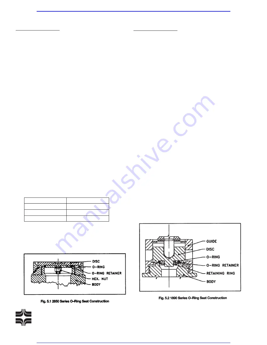
Series 1890 and 1892
1. Refer to Figure 2.2 for construction details.
2. Visually inspect all parts to be assembled. Replace all
gaskets. Lubricate all threaded and mating surfaces
with
Bostik Never Seez
(or equivalent).
3. Examine seat of body and disc for any marks or surface
imperfections that may reduce seat tightness. If relap-
ping is necessary, refer to the section on Lapping.
4a.(Metal Seat Only) Loosely assemble body and guide.
Insert disc in guide and verify that guide turndown from
disc contact is 1/16 to 1/4 turn. For set pressure under
100 psig, 1/8 turndown maximum is required. Remove
disc.
4b.(O-Ring Seat Only) It is recommended that O-ring/disc
subassembly be replaced rather than attempt removal
of retaining ring. Do not use a metal seat guide in
O-ring seat seal valves.
5. Tighten guide to body with 1/4” dia. bar inserted through
guide exit holes with approximate torque of 20 ft. Ibs.
6. Insert disc and install lift stop. Verify that available disc
lift is greater than .085”.
7. Place stem shoulder over retaining ring. Install spring
and spring buttons on stem and insert entire assembly
into bonnet/spring adjusting screw subassembly. The
lower subassembly with body gasket can then be
assembled and tightened to approximately 40 ft. Ibs.
torque.
8. Hand tighten adjusting screw until slight spring com-
pression occurs.
Farris Engineering
Division of Cur tiss-Wright Flow Control Corporation
INLET SIZE
# NOTCHES
3/4
″
6
1, 1 1/2
″
22
2, 3
″
33
Visit www.boighill.com to request a quote.
Visit www.boighill.com to request a quote.


