background image

47 


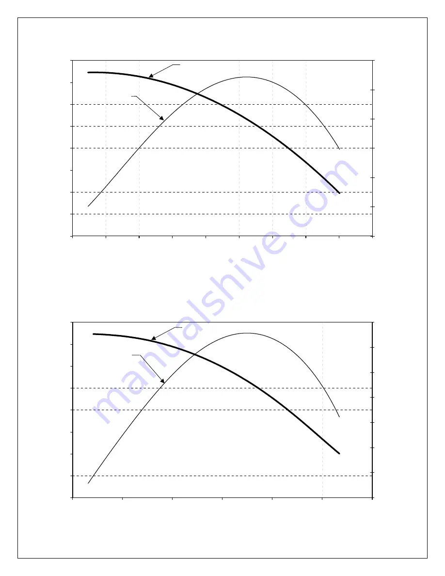
NYB 18PLR-6.0-60-9

0.0

2.0

4.0

6.0

8.0

10.0

12.0

14.0

16.0

3,000

3,500

4,000

4,500

5,000

5,500

6,000

6,500

7,000

7,500

FLOW RATE (cfm)

STATIC PRESSURE (in H

2

O)

11.0

11.5

12.0

12.5

13.0

13.5

14.0

BRAKE HORSEPOWER

STATIC PRESSURE

BRAKE 

HORSEPOWER

Figure 400.7.6

6000 CFM, 9.1" H

2

O, 3500 RPM, 13.6 BHP

NYB 18PLR-8.0-60-9

0.0

2.0

4.0

6.0

8.0

10.0

12.0

14.0

16.0

4,000

5,000

6,000

7,000

8,000

9,000

10,000

FLOW RATE (cfm)

STATIC PRESSURE (in H

2

O)

15.0

15.5

16.0

16.5

17.0

17.5

18.0

18.5

BRAKE HORSEPOWER

STATIC PRESSURE

BRAKE 

HORSEPOWER

Figure 400.7.7

8000 CFM, 9.1" H

2

O, 3500 RPM, 18.2 BHP

Содержание Gold GS10

Страница 1: ... and Maintenance Installation Operation and Maintenance Farr Air Pollution Control PO Box 9080 3501 North Airport Road Jonesboro Arkansas 72401 1 800 479 6801 1 800 222 6891 Fax wwwfarr com apc Customer Customer Location Location Job Local Rep Rep Phone Document C 1000 21 Rev D ...

Страница 2: ...PLATFORM LADDER 13 SECTION 320 ATTACHING DUCT WORK TO YOUR GOLD SERIES 14 320 1 INLET DUCT DESIGN 15 320 2 INLET FLANGES 16 320 3 REMOTE MOUNT FAN DISCHARGES 16 320 4 TOP MOUNT FAN DISCHARGES 16 320 5 DISCHARGE HOPPER FLANGE 16 SECTION 330 FIELD UTILITY CONNECTIONS 17 330 1 MOTOR CONNECTIONS 18 330 2 TIMER CONTROL 19 330 3 SOLENOIDS 19 330 4 DIFFERENTIAL PRESSURE DP CONNECTIONS 21 330 5 COMPRESSED...

Страница 3: ... 400 8 STARTUP PROCEDURE 49 400 9 SHUTDOWN PROCEDURE 50 400 10 RECOMMENDED TIMER SETTINGS 50 SECTION 500 PREVENTIVE MAINTENANCE AND TROUBLESHOOTING 51 500 1 FILTER ELEMENTS 51 500 2 HOPPER 51 500 3 FAN MOTOR LUBRICATION 51 500 4 SOLENOID AND DIAPHRAGM VALVES 51 500 5 AUTOMATIC TIMER CONTROL IF EQUIPPED 52 500 6 CLEANING AND REPAIR 52 500 7 INSPECTION LOG 52 500 8 SUGGESTED PREVENTATIVE MAINTENANCE...

Страница 4: ... Lock __________________________________________________ Screw Conveyor __________________________________________________ Dust Level Indicator __________________________________________________ High Hopper Level Probe __________________________________________________ Support Structure __________________________________________________ Determinator Remote Display Panel ___________________________...

Страница 5: ... that is used to eliminate dust contaminants from the environment making the facility or plant a healthier and safer work place This unit has been assembled using only quality materials and labor This machine has been checked to make sure that it is operational for you at the time of installation Prior to installing your equipment thoroughly read and understand this manual Locate all parts and ens...

Страница 6: ...arr direct at 1 800 479 6801 Part numbers for these decals are listed in the spare parts list in section 700 This piece of equipment may contain one or more safety guards to protect the operator s from injury It is the owner operator s responsibility to maintain the integrity of these guards and ensure that they are in place when the equipment is in operation WARNING DO NOT attempt to operate or m...

Страница 7: ...rds associated with equipment that are considered confined spaces 100 3 Lock out Tag out Requirements Control of this equipment must be in accordance with OSHA Standard 1910 147 Control of Hazardous Energy Lock out Tag out This standard requires employers to establish a program and utilize procedures for affixing appropriate lock out tag out devices to energy isolating devices and to otherwise dis...

Страница 8: ...asic understanding of common hand tools Besides a common set of hand tools a crane fork lift and or chain fall will be required to position the fan and motor on top of the unit clean air plenum and lift heavier components into position Farr must rely on the skill and expertise of its customers and the customer s installation contractor to ensure that all electrical connections are made correctly a...

Страница 9: ...collector Inspect all items for apparent damage Immediately report any shortages or obvious damage to the carrier and to your local Farr Representative or call Farr at 1 800 479 6801 When all skids are completely unpacked check all items received against the material list on the project drawing and or the packing list if any sent with the shipment Further inspect the unit and components for hidden...

Страница 10: ...sonry Bit Anchoring to floor 7 Hammer Installing anchors 8 Pliers General use 9 Wire Cutters Electrical connections 10 Wire Nuts Electrical connections 11 Electrical Tape Electrical connections 12 Extension Cord General use 13 Conduit Electrical connections 14 or larger black iron pipe or equivalent Compressed air connections 15 Fittings for items 13 14 Compressed air and electrical connections 16...

Страница 11: ...t them to the corner support brackets Locate the cross braces and bolt them to the support legs If your collector contains knee braces bolt one end to the support leg and the other end to the corner support bracket Note Do not tighten any of the bolts until all bolts have been started 310 4 Hopper Support Structure Assembly Lift the completed hopper support structure assembly with a forklift or ch...

Страница 12: ...e the flanges or rope caulk Ensure that the orientation of the collector is as desired for your installation Note On GS6 10 20 collectors ensure that the Match Line label s on the filter module line up with the Match Line label s on the hopper s Figure 310 3 Attach the filter module to the hopper using 3 8 16 thread cutter screws Figure 310 3 Use a drift or alignment pin to align holes as necessar...

Страница 13: ... the 4 clamps are secured the drum lid gasket seals tightly against the top surface of the drum Tighten the drum ring screw If you have a negative pressure drum kit place the drum lid on top of the drum with the gasket surface contacting the top surface of the drum Figure 310 7 310 8 Platform Ladder If equipped lift the platform assembly into position and install using the hardware provided Lift a...

Страница 14: ... SPA 6 18 4 1 8 4 1 8 26 1 4 1 1 8 1 1 8 26 1 4 3 SPA 6 18 60 24 9 SPA 6 54 4 1 8 1 1 8 62 1 4 3 SPA 6 18 26 1 4 4 1 8 96 24 15 SPA 6 90 90 1 1 8 3 8 16 UNC 3 8 16 UNC 3 8 16 UNC Figure 320 1 SINGLE MODULE INLET Figure 320 2 DOUBLE MODULE INLET Figure 320 3 TRIPLE MODULE INLET 22 1 6 SPA 4 24 SIDE OUTLET FLANGE Figure 320 4 10 SPA 4 40 3 8 16 UNC 38 3 8 16 UNC 22 6 SPA 4 24 HALF PANEL SIDE OUTLET ...

Страница 15: ...ilters to be re entrained into the air stream In figure 320 9 the RECOMMENDED design shows a straight section of duct that is at least 2 duct diameters long before entering the inlet The air direction will cause the dust to be evenly distributed to all of the filters in the collector In the NOT RECOMMENDED design the duct is not long enough to allow the air to straighten out before entering the in...

Страница 16: ...he panel and frames Either the side panels on the upper section of the dust collector or top panels can be removed Figure 320 4 is the bolt pattern for the full sized side panel while Figure 320 5 is for the half sized side panel Figure 320 6 and 320 7 are for the full and half sized top panels respectively When attaching ductwork to these flanges always be sure to caulk or place gasket between th...

Страница 17: ...E 330 3 Figure 330 1 Field Utility Connections GROUND HIGH DP JUMPER LOW DP 90 PSI MIN COMPRESSED AIR 1 NPT SOLENOID TO DIAPHRAGM VALVE CONNECT TO MAGNEHELIC GAGE IF YOU DO NOT HAVE AIRLINE CONNECTIONS ON YOUR TIMER 1 4 OD PNEUMATIC TUBE ELECT WIRE 1 NPTAIR LINE HOT 1 PER SOLENOID COMMON ...

Страница 18: ...d only make these connections 18 230 V 208 V Camfil Farr P N SIZE P N PANEL BK Camfil Farr P N SIZE P N PANEL BK HP HP AMPS AB P N AMPS AB P N 207267201 207267401 1 5 1 5 207267202 207267402 2 2 207267203 207267403 3 3 207267204 207267404 5 NA 16 AB100C16L10 207267205 207267405 7 5 5 23 AB100C23L10 207267206 207267406 10 7 5 30 AB100C30L10 12 37 193 EA1HC 207267207 207267407 15 10 43 AB100C43L10 1...

Страница 19: ...tached to all of the solenoids called the Common The Common is factory pre wired on the solenoids therefore only one connection will need to be made Once the solenoid has been wired the corresponding wires will then be attached to the control board as shown in Figure 330 3 2 The Common will share a terminal with the L2 terminal 120 volt return power line Note The Controllers will have a separate C...

Страница 20: ...s make sure the solenoids are connected to diaphragm valves on different headers as shown in Figure 330 3 3 20 Figure 330 3 3 DOUBLE UP TIMER OUTPUTS AIR LINE 1 4 OD TUBE SOLENOID BOX ELECTRICAL TIMER DIAPHRAGM SOLENOID TIMER OUTPUT HEADER HEADER GS2 2 6 10 10 N GS4 4 6 10 10 N GS6 6 6 10 10 N GS8 4 6 10 10 N GS10 5 6 10 10 N GS12 6 6 10 10 N GS16L 8 10 10 10 N GS16 SQ 4 10 10 10 N GS20 5 10 10 10...

Страница 21: ...ual shut off valve a filter separator an air regulator and a pressure gauge all located close to the unit Farr recommends that the compressed air supply be kept at a dew point of 850 F Make provisions for draining any condensate from the air reservoir with an automatic tank drain or by other means Total air consumption is variable and is dependent on the type and concentration levels of airborne d...

Страница 22: ... off valve 22 Gold Series Dust Collector Air Consumption 1 Diaphragm Valve 0 10 20 30 40 0 10 20 30 40 50 60 70 OFF TIME sec Compressed Air Consumption CFM 200 msec ON TIME 150 msec ON TIME 100 msec ON TIME 100 150 200 100 150 200 5 27 0 31 8 37 2 38 4 72 0 92 4 10 13 5 15 9 18 6 19 2 36 0 46 2 15 9 0 10 6 12 4 12 8 24 0 30 8 20 6 8 8 0 9 3 9 6 18 0 23 1 25 5 4 6 4 7 4 7 7 14 4 18 5 30 4 5 5 3 6 2...

Страница 23: ...inkler There is one pipe connection for each sprinkler head 23 Figure 330 6 2 shows an internal sprinkler system which is used on large GS collectors where necessary Two or more sprinkler heads connect to vertical pipes which are connected to a pipe that Gold Series Dust Collector Air Consumption 1 1 2 Diaphragm Valve 0 10 20 30 40 50 60 70 80 90 100 0 10 20 30 40 50 60 70 OFF TIME sec Compressed ...

Страница 24: ... to the sprinkler connection coupling s Turn on water supply and inspect all connections for leaks Note Water leaks in the collector will cause cartridge failure and hopper flow problems 24 SPRINKLER CONNECTION COUPLING SEE TABLE 330 6 1 FOR CONNECTION SIZE AND NO OF CONNECTIONS SPRINKLER HEAD SEE TABLE 330 6 1 FOR QUANTITY Figure 330 6 2 Model Designation No Sprinkler Heads Flow Rate Gal Min Size...

Страница 25: ...ciated hazards 3 The complete dust collection system should be designed in a manner that conforms to the NFPA standards and recommendations in order to minimize the risks associated with a deflagration Farr does not participate in the design of the dust collection system and makes no guarantee that the inclusion of an explosion vent on the dust collector will satisfy the requirements of the NFPA r...

Страница 26: ...flagration are not permitted Vents should function dependably Closures should not be hindered by deposits of snow ice paint corrosion or debris or by the buildup of deposits on their inside surfaces Closures should not be bonded to the enclosure by accumulations of paint The materials that are used should be chosen to minimize corrosion Clear space should be maintained on both sides of a vent to e...

Страница 27: ...n 20ft long have a cross sectional area larger than the vent and should not interfere with the operation of the vent Bird screens or weather hoods must be low restriction and their affect should be taken into consideration when sizing the vent area 340 10 Vent Inspection and Maintenance Farr incorporates two styles of explosion vents on their dust collectors One is a rupture diaphragm and the othe...

Страница 28: ...hem off the clamp bar channels Clean the surface of the tubesheet in the areas where the filter gasket forms a seal 5 Remove a new cartridge from the shipping carton taking care not to cut or otherwise damage the filter media Grasp the new cartridge by the top metal pan and set it onto the clamp bar channels Holding the cartridge level slide it forward taking care not to drag the gasket along the ...

Страница 29: ...carbons or similar substances the life of the filters can be greatly increased by pre coating Pre coating Procedure 1 Ensure the filter cartridges are correctly installed 2 Install a clean empty discharge container under the unit 3 If a Safety Monitoring Filter SMF is installed it must first be removed from the system 4 Disable the dust collector so that it does not pulse while the pre coat is bei...

Страница 30: ...tlet ducting SMF housing and discharge container Discard according to local codes and procedures 11 Re enable the collector by either opening the compressed air line or turning on the power to the timer control see step 4 15 The system is now ready for operation 30 Model Designation Pre coat Amount Lbs GS 2 18 GS 4 36 GS 6 54 GS 8 72 GS 10 90 GS 12 108 GS 16 144 GS 20 180 GS 24 216 GS 36 324 Table...

Страница 31: ...m Operation Incoming dust laden air enters the inlet plenum where a baffle forces large or heavy particles to drop out of the air stream and fall into the hopper The clean air passes through the filter media from the outside to the inside of the filter cartridge and exits through the open top of each filter cartridge The air then flows from the filters into the clean air plenum where it enters the...

Страница 32: ...he differential pressure DP and pulsing accordingly can maintain the dust cake with minimal increase in pressure By pre coating your filter with a special dust at start up you can increase initial efficiency of your collector see Section 360 PRECOATING OF FILTERS 400 2 Filter Cleaning The Gold Cone cartridge elements are sequentially cleaned by back flushing with air This momentary airflow reversa...

Страница 33: ...pes The size of the diaphragm valves is 1 or 1 1 2 depending on the size of the collector See Section 700 Replacement Parts Lists for the size of diaphragm valves on your collector PULSEJET BLOW PIPE Each pulsejet blowpipe contains one 1 nozzle for each cartridge These nozzles are positioned above and directed into the opening of the filter cartridge As the pulse of air reaches the nozzle it is ac...

Страница 34: ...t switch will change the setup mode to Time On Setup Time On Setup Time On Setup sets the solenoid on time The display will indicate the currently programmed time on setting This is measured in milliseconds Using the Up and Down buttons the value may be changed The value may be set between 10 msec and 600 msec in 10 msec increments Pressing the Up and Down buttons simultaneously for approximately ...

Страница 35: ...Setup mode if a pressure module is installed or to Process when no pressure module in available Auto Alarm Reset Setup The Auto Alarm Reset Setup available only when a pressure module is installed allows the auto alarm reset time to be selected This value may be set between zero and 255 seconds The factory default value is five seconds When the auto alarm reset is enabled by shorting the auto alar...

Страница 36: ...36 SELECTOR SWITCH NEMA 4X ENCLOSURE OFF ON DEMAND CONTINUOUS Figure 400 4 1 Dwyer DCT1000 Timer Enclosure ...

Страница 37: ...HIGH LIMIT LOW LIMIT HIGH ALARM LOW ALARM CYCLE DELAY MIN DOWN TIME CYCLES MIN AUTO ALARM RESET SEC LAST OUTPUT RUN ALARM RESET MANUAL OVERRIDE UP DOWN SELECT SETUP STATUS DAISY CHAIN IN OUT DWYER INSTRUMENTS MICHIGAN CITY IN HIGH LIMIT COM LOW LIMIT ALARM MODE MAN OVR DT CLN ALARM RESET COM COM TB3 TB2 4 20 MA OUTPUT l l NC l l NC 4 20 MA SOURCE EXTERNAL INTERNAL ALARM CONTACTS POWER ON TB4 TB5 D...

Страница 38: ...UT OUTPUT ALARM BYPASS INPUT VOLTAGE DP CYCLE DOWN OR BYPASS MODE SELECT OPTIONAL 25 DIA MOUNTING HOLE 4 PLACES 8 75 8 25 250V 3 AMP FUSE SOURCE REMOTE ALARM INPUT OPTIONAL INPUT OPTIONAL REMOTE ALARM 6 25 6 88 L1 L2 1 2 3 4 5 7 6 8 9 10 FIVE COIL SOLENOID ENCLOSURE SHOWN ACTUAL ENCLOSURE MAYVARY FROM 2 TO 10 COILS PER ENCLOSURE 20 OUTPUT MODELS ARE IDENTICAL EXCEPT THEY HAVE 20 OUTPUTS 120 1 50 6...

Страница 39: ...ES NO DISPLAYFREEZES AT P X X OPERATING MODE DISPLAYS SETUP ON STARTUP AND AFTER RESET DISPLAYS P X X WHEN RUNNING OUTPUT X EXIT DO YOU WANT EXIT PROGRAM MODE PRESS VALUE KEY FOR YES PRESS ITEM UP KEY TO MOVE BACK TO PREVIOUS OPTIONS DO YOU WANT PROGRAM THE CLOCK REQUIRES I O BOARD PRESS VALUE KEY FOR YES PRESS ITEM DOWN KEY TO ADVANCE TO NEXT OPTION PROGRAM CLK YES NO YES NO ITEM ITEM VALUE ITEM ...

Страница 40: ...ALM H X X ACCEPT OFF XXX PULSE FREQUENCY OFF TIME RANGE 7 0 999 SEC ACCEPT TO C ITEM ITEM ITEM ITEM ITEM ITEM ITEM VALUE ITEM ITEM VALUE ITEM VALUE VALUE ITEM VALUE ITEM VALUE ITEM VALUE ITEM VALUE CHANGE CHANGE CHANGE CHANGE CHANGE TO A WHEN CYCLE DOWN IS ENABLED USE THE UP AND DOWN VALUE KEYS TO SET THE NUMBER OF CLEAN DOWN CYCLES UP TO AMAX OF 15 THE IDC WILL STEP THROUGH THE CYCLE AND SHUT ITS...

Страница 41: ...nning with the next to last row cleaned Installation Connect Line Input Power AC voltage to the terminals marked L1 and L2 DC voltage to the Negative and Positive terminals Connect the output terminals to the pilot valve solenoid coils Connect common side of the coil AC voltage to terminal L2 DC voltage to the Positive terminal Note Line voltage must match coil voltage Blowdown If the blowdown fea...

Страница 42: ...ED indicator In the locked position the Digital Readout will display the last setting which is the number of blowdown cycles programmed To check a specific function setting push the Select button to illuminate the desired function LED the setting is then shown on the Digital Readout 42 L1 GREEN L2 SELECT ADJUST B2 B1 P1 P2 P3 ON TIME OFF S OFF TIME LOCKED VALVE 1 25 2 26 3 27 4 28 5 29 6 30 7 31 8...

Страница 43: ...t 30 valves illustrated STEP 4 BLOWDOWN CYCLES Press the Select button until the OFF S LED indicator is illuminated then press the Adjust button until the required number of BLOWDOWN CYCLES is shown on the Digital Readout 6 cycles illustrated Note Blowdown will not occur if the collector is operating at below the high pressure drop setting unless the controller is in the continuous cleaning mode S...

Страница 44: ...rflow rate horizontal axis The brake horsepower curve light designates the actual horsepower right axis required from the fan 44 NYB 126GI 1 0 60 8 0 0 2 0 4 0 6 0 8 0 10 0 12 0 0 200 400 600 800 1 000 1 200 1 400 1 600 1 800 FLOW RATE cfm STATIC PRESSURE in H 2 O 1 0 1 5 2 0 2 5 3 0 3 5 4 0 BRAKE HORSE POWER STATIC PRESSURE BRAKE HORSEPOWER Figure 400 7 1 1000 CFM 7 9 H2O 3500 RPM 2 4 BHP 5 6 7 8...

Страница 45: ... 4 4 4 5 BRAKE HORSEPOWER STATIC PRESSURE BRAKE HORSEPOWER Figure 400 7 3 2000 CFM 9 1 H2O 3500 RPM 4 3 BHP NYB 146GI 1 5 60 10 0 0 2 0 4 0 6 0 8 0 10 0 12 0 14 0 16 0 500 700 900 1 100 1 300 1 500 1 700 1 900 2 100 2 300 2 500 FLOW RATE cfm STATIC PRESSURE in H 2 O 2 0 3 0 4 0 5 0 6 0 7 0 8 0 BRAKE HORSEPOWER STATIC PRESSURE BRAKE HORSEPOWER Figure 400 7 2 1350 CFM 11 1 H2O 3500 RPM 5 0 BHP ...

Страница 46: ...6 6 8 BRAKE HORSEPOWER STATIC PRESSURE BRAKE HORSEPOWER Figure 400 7 4 3000 CFM 9 1 H2O 3500 RPM 6 4 BHP NYB 18PLR 4 0 60 9 0 0 2 0 4 0 6 0 8 0 10 0 12 0 14 0 16 0 2 000 2 500 3 000 3 500 4 000 4 500 5 000 FLOW RATE cfm STATIC PRESSURE in H 2 0 7 0 7 5 8 0 8 5 9 0 9 5 BRAKE HORSEPOWER STATIC PRESSURE BRAKE HORSEPOWER Figure 400 7 5 4000 CFM 9 1 H2O 3500 RPM 9 1 BHP ...

Страница 47: ...3 5 14 0 BRAKE HORSEPOWER STATIC PRESSURE BRAKE HORSEPOWER Figure 400 7 6 6000 CFM 9 1 H2O 3500 RPM 13 6 BHP NYB 18PLR 8 0 60 9 0 0 2 0 4 0 6 0 8 0 10 0 12 0 14 0 16 0 4 000 5 000 6 000 7 000 8 000 9 000 10 000 FLOW RATE cfm STATIC PRESSURE in H 2 O 15 0 15 5 16 0 16 5 17 0 17 5 18 0 18 5 BRAKE HORSEPOWER STATIC PRESSURE BRAKE HORSEPOWER Figure 400 7 7 8000 CFM 9 1 H2O 3500 RPM 18 2 BHP ...

Страница 48: ... 23 0 BRAKE HORSEPOWER STATIC PRESSURE BRAKE HORSEPOWER Figure 400 7 8 10000 CFM 9 1 H2O 3500 RPM 22 7 BHP NYB20PLR 12 0 60 9 0 0 2 0 4 0 6 0 8 0 10 0 12 0 14 0 16 0 18 0 6 000 7 000 8 000 9 000 10 000 11 000 12 000 13 000 14 000 FLOW RATE cfm STATIC PRESSURE in H 2 O 24 0 25 0 26 0 27 0 28 0 29 0 30 0 31 0 BRAKE HORSEPOWER STATIC PRESSURE BRAKE HORSEPOWER Figure 400 7 9 12000 CFM 7 8 H2O 3500 RPM...

Страница 49: ...even if the collector is insulated Activate the collector fan and dust removal devices Make sure the fan rotates in the direction indicated by the wheel rotation arrows on the fan Refer to your General Dimensions drawing for the Air to Cloth Ratio ACR for your collector Use the graph Figure 400 8 1 to determine the pressure drop Adjust the damper until the magnehelic gauge registers the pressure d...

Страница 50: ...ves high dust loads and dust that does not easily release from the cartridge On applications with light dust loads this value can be reduced to conserve compressed air Pulse Frequency off time 15 seconds Increasing this value will decrease compressed air consumption Decreasing this value will increase compressed air consumption You would decrease this value if your application involves high dust l...

Страница 51: ...l inhibit performance of the collector 500 3 Fan Motor Lubrication The most common cause of premature bearing failure is improper lubrication The fan motor provided with Gold Series dust collectors may vary Farr often provides the fan with the collector but many times the fan is provided by other sources If Farr provided the fan it will be one of two types One type has sealed for life bearings and...

Страница 52: ... Control 500 6 Cleaning and Repair The external and internal surfaces of the unit should be treated as any other painted metal surface subject to corrosion Examine the unit for any damage to the surface coating and repair as necessary Keep the external surface clean to prevent the possibility of hidden damage occurring Periodic application of a quality automotive wax will prolong the life of paint...

Страница 53: ... Y N Y N Y N Y N Y N Are solenoids operating Y N Y N Y N Y N Y N Are Diaphragm valves firing Y N Y N Y N Y N Y N Hopper discharge device operating Y N Y N Y N Y N Y N Any visible stack emissions Y N Y N Y N Y N Y N Weekly Record compressed air pressure PSIG PSIG PSIG PSIG PSIG Clean compressed air filter tap Check tubesheet for filter leaks Check that hopper is empty Monthly Are there leaks in acc...

Страница 54: ...rtridge appearance Verify accuracy of temperature indicating equipment Weekly Check pressure drop indicating equipment for plugged lines Inspect fans for corrosion and material buildup Check drive belts for wear and tension Inspect and lubricate appropriate items Spot check for filter cartridge leaks Check hoses and clamps Check accuracy of indicating equipment Monthly Inspect housing for corrosio...

Страница 55: ... Check diaphragms replace or repair Check solenoid valves replace or repair Pulsing valve failure Consult Customer Service 1 800 479 6801 See sections following Timer Controller Failure Verify controller is operational Check for appropriate power connections Check to see if timer is indexing to all contacts Check output on all terminals Check accuracy of magnehelic gauge if applicable Controller t...

Страница 56: ...stall alternate media that can tolerate higher temperature Temperature too high Consult Customer Service 1 800 479 6801 Restart collector using suggested procedure in manual Damper fan and slowly open as system starts up Preheat the collector before start up Use pre coat dust to season the cartridges Improper start up of collector Consult Customer Service 1 800 479 6801 Check fan damper and fan sp...

Страница 57: ... Customer Service 1 800 479 6801 Open drain valve on air header to see if water comes out Check to see if compressed air supply has an air dryer installed Verify air dryer is rated for 85 degree dew point Replace desiccant in the dryer Replace dryer Install moisture resistant or washable cartridges Water moisture in compressed air Consult Customer Service 1 800 479 6801 Check ductwork on inlet and...

Страница 58: ...rger than GS10 Compressed air supply line too small Consult Customer Service 1 800 479 6801 Check diaphragm replace or repair Check pilot valves replace or repair Diaphragm valves not working Consult Customer Service 1 800 479 6801 Replace rings in compressor Check for worn components Rebuild compressor or consult compressor manufacturer Upgrade to compressor which can handle larger air volume Com...

Страница 59: ...r Service 1 800 479 6801 Remote mount controller away from dust collector Vibrations causing failure Consult Customer Service 1 800 479 6801 Replace board consult replacement parts list for appropriate type part Bad control board Consult Customer Service 1 800 479 6801 Confirm accuracy of the gauge and adjust as necessary Sensor hoses are backwards switch connections of tubing Replace magnehelic g...

Страница 60: ...omer Service 1 800 479 6801 Confirm the screw airlock speed for application make adjustment Check for correct rotation of blades reverse direction if necessary Lubricate bearings or motor if applicable Replace bearings or motor if applicable Replace gasket or caulk on hopper flange Confirm correct application of airlock replace if necessary Refer to airlock manual for further information Consult a...

Страница 61: ... inlet air damper fan Install filter cartridges of different media type Increase media area of filter cartridges Install additional modules to reduce Air to Cloth ratio Confirm appropriate location of pickup points and hoods Install pre filter to collect larger particles Cyclone Application too abrasive Consult Customer Service 1 800 479 6801 Measure air temperature in collector and compare to des...

Страница 62: ...or your type of controller Cleaning cycle too frequent Consult Customer Service 1 800 479 6801 Measure air temperature in collector and compare to design Use dilution air to reduce temperature in collector change fans Install alternate media that can tolerate higher temperature Temperature too high Consult Customer Service 1 800 479 6801 Replace cartridges with correct filter media for application...

Страница 63: ...ndard Change hood type to improve collection performance Reposition collection point or hood to improve performance Consult installer of ductwork Collection point incorrectly positioned Consult Customer Service 1 800 479 6801 Check to see if the fan is turned to the on position Check required fan power requirement vs what is supplied Check that power supply is hot Incorrect wheel rotation correct ...

Страница 64: ...d cartridges Consult Customer Service 1 800 479 6801 Tighten wheel of fan Replace wheel of fan Balance or adjust fan wheel Consult manufacturer of fan Fan impeller hitting the inlet of the fan Consult Customer Service 1 800 479 6801 Lubricate bearings Replace bearings Consult manufacturer of fan Bad bearings in the fan Consult Customer Service 1 800 479 6801 Damaged wheel replace or repair wheel D...

Страница 65: ...Abnormal Noise continued Normal noise level of fan operation Consult Customer Service 1 800 479 6801 Install explosion vents Replace all blown or open vents not reusing or adjusting latches Install a spark arrester to stop sparks before entering collector Install a high efficiency Cyclone to catch sparks Install a sprinkler system inside the collector Install a fire protection system in the ductwo...

Страница 66: ...inside the inlet plenum Thoroughly check all boxes before discarding Missing Parts Consult Customer Service 1 800 479 6801 Locate and seal any dust leakage points in the collector Caulk any leaking flanges or panels Insert any missing bolts or fittings Replace door gaskets if leaking Check and repair door lock mechanism if necessary Weld or caulk any holes or gaps in welded seems Collector leaks d...

Страница 67: ... Farr to replace cross braces Consult Customer Service 1 800 479 6801 Check drain plugs close if open Check hoses in between headers and purge pipes replace Check and repair diaphragm valves Air header leaks Check connection to compressed air supply line repair if necessary 67 ...

Страница 68: ...ity is the upward air stream speed calculated by dividing the open cross sectional area of the dust collector less the area of the filter bottom into the full volume of the exhaust fan ACFM Ft2 Feet per Minute Ref Interstitial Velocity Clean Air Plenum The dust collector area through which gases are directed located on the clean side of the filter media Collection Efficiency The measure of a dust ...

Страница 69: ...ents calculated at its highest value Ref Can Velocity for formula Magnehelic Gauge An instrument used to measure differential pressure drop Manometer A U shaped tube filled with a specific liquid The difference in height between the liquid in each leg of the tube gives the difference in pressure on each leg of the tube Used to monitor differential pressure Micron µm A unit of length 1 1000 of one ...

Страница 70: ...ning and is again captured by the same or an adjacent filter media Rotary Airlock Valve Device having a star wheel rotor designed to provide an air tight seal between the negative or positive pressures of the collector and the outside atmosphere Screw Conveyor A revolving screw operating in a fixed trough for conveying material from one point to another Note Should a screw conveyor be used in a du...

Страница 71: ...High Efficiency Wide Pleat 200 Square Foot Dura Pleat Cartridges 205637 001 DPS Dura pleat Standard Spun Bond Polyester 205637 002 DPA Dura pleat Aluminized Finish Static Drain 205637 003 DPO Dura pleat Oleophobic Treatment 205637 004 DPT Dura pleat with Teflon Membrane FILTER ACCESSORIES 208721 001 Cartridge Removal Tool AFTER FILTERS 049880 005 30 30 Pre filter 24x24x2 049880 006 30 30 Pre filte...

Страница 72: ...rd without pressure module 6 Terminal 208026 010 Dwyer DCT1010 Replacement Board without pressure module 10 Terminal 208026 022 Dwyer DCT1022 Replacement Board without pressure module 22 Terminal 208220 006 Dwyer DCT1006 Replacement Board with pressure module 6 Terminal 208220 010 Dwyer DCT1010 Replacement Board with pressure module 10 Terminal 208220 022 Dwyer DCT1022 Replacement Board with press...

Страница 73: ... DECALS 205821 001 ENTRAPMENT 6 X3 205822 001 EXPLOSION 6 X3 205819 001 SAFETY INSTRUCTIONS 3 X6 205817 001 WARNING 3 X6 205965 001 WARNING AUTO START 205818 001 WARNING COMPRESSED AIR 2X4 205820 001 WARNING LOCKOUT 3 X6 205816 001 DANGER BLADES 2 X4 207172 001 CONTAINS GOLD SERIES HARDWARE 205516 001 FARR GOLD SERIES 1 X4 5 205668 001 FARR APC 32X10 205515 001 FILTERMAN MISCELLANEOUS 074492 000 R...

Страница 74: ... Box 8 solenoids GS32 GS48 GS84 067497 010 Solenoid Box 10 solenoids GS60 GS84 GS96 GS120 9 067497 012 Solenoid Box 12 solenoids GS36 GS72 GS96 067497 008 Solenoid Box 8 solenoids GS84 10 067497 012 Solenoid Box 12 solenoids GS96 11 084415 002 Solenoid Valve Single Included in items 9 10 205745 001 Clamp Bar Right hand 2 filters deep 205745 002 Clamp Bar Right hand 4 filters deep 205745 003 Clamp ...

Страница 75: ...75 ...

Страница 76: ...can be replaced rather than replace the entire solenoid box 11 10 9 Bulkhead Fitting Dresser Nut Lock Ring Note Connects to Item 5 7 Figure 700 1 1 Note Connects to Item 4 12 13 20 26 21 23 24 22 14 18 19 16 8 6 5 27 15 6 6 3 17 2 1 4 8 25 ...

Отзывы: