background image

9

Assembly - 5010, 6010 & 6610 Snowblower

Assembly Instructions 

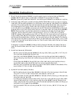
1.  Mount the discharge spout (816667) using the spout spacers and spout clamps (816619 & 

815586). Bolt the spout ring on snowblower. Lubricate the spout ring and clamp.  
NOTE: A hydraulic cylinder and hose kit to control the spout deflector is available as an option.

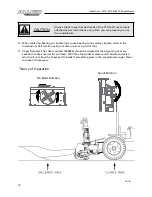
2.  Hitch Assembly: With right and left hitch tubes (907127 & 907128) turned as shown in drawing, 

slide them into the sleeve welded to the main body. These tubes are adjustable to four different 
positions. The correct position for each individual tractor will be determined when mounting 
the snowblower on the tractor. These tubes are connected to the snowblower with a 3/4" x 
3-1/4" (19 x 83 mm) pin (965624) and a hair pin clip (12779). Bolt the left (815218) and the right 
(815219) hitch arms to the outside of the clevises on the hitch tubes using the lift pins (965809). 
NOTE: Pins should be turned to the outside. Do not tighten any hardware until assembly is 
complete. Join the top of the hitch arms by bolting a 1" O.D. x 2-1/4" (25 x 57 mm) spacer 
(906770) between the top plates using a 3/4" x 4" (19 x 102 mm) bolt and lock nut through the 
lower outside holes. Bolt the hitch top bar (907139) between the same plates using the same 
bolt through the welded tube on the bar. Use the inside holes on the top plates for the top bar. 
The other end of the hitch top bar bolts to the top of the blower fan housing with a 1/2" x 1-3/4" 
(13 x 44 mm) hex bolt, lock washer and hex nut. Use the same hole position as the hitch tubes. 
Tighten all hardware. 
 
A Category 1 top link pin (965807) is fitted in the top holes of the hitch arm plates. This pin is 
used for standard three-point hitch only. The bushing in the lower holes is used for the Quick 
Hitch.

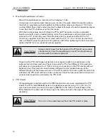
3.  Hand Crank Assembly: (Standard)


- Bolt the crank mounting bracket (965634) to the top of the hitch using 3/8" x 1-1/4" (10 x 32 

mm) hex bolts, lock washers and hex nuts.


- Insert the crank handle (906667) through the mount and through the bracket welded to 

the main housing. Lock the crank in place using a washer and roll pin on each side of the 
bracket.


- Thread the cable (965616) through the hole in the crank tube to even lengths and wrap 

around the tube to each side of the hole four turns in opposite directions.


- With the spout turned forward, fasten the cable to the bracket welded to the bottom of the 

spout using a 1/4" (6 mm) cable clamp (961658). 

4.  Hydraulic Control Assembly: (Option)


- Bolt the hydraulic swivel assembly (965626) to the back of the fan housing on the left side 

using 1/2" x 1-1/4" (13 x 32 mm) hex bolts, lock washers and hex nuts.


- Bolt the cylinder mounting bracket (965628) to the back of the fan housing on the right side 

using the same size hex bolts.


- Turn the spout forward and the center of the swivel arm in line with the spout center. With 

the spout and swivel arm in this position, wrap the cable (965627) around the spout and 
clamp to both ends of the swivel arm and to the bracket welded to the bottom of the spout 
using 3/16" (5 mm) cable clamps (965806).


- Use a standard 8" (203 mm) stroke cylinder (20-1/4" (51 cm) min., 28-1/4" (72 cm) max. pin 

centers).

Содержание ALLIED 5010

Страница 1: ...Snowblower Models 5010 6010 6610 OPERATOR AND PARTS MANUAL 032014 FK312...

Страница 2: ......

Страница 3: ...rawings 14 Snowblower Drawings 14 Snowblower Parts List 16 PTO Drawing 20 PTO Parts List 21 1 75 x 5 Cylinder Drawing and Parts List 22 2 0 x 8 Cylinder Drawing and Parts List 23 Shipping Kit and Bund...

Страница 4: ...ength adjustable hitch is standard on all models Also available is an optional hydraulic spout control There is a shear bolt on the auger and on the PTO shaft to protect the machine from damage if a l...

Страница 5: ...commended precautions The safety alert symbol means ATTENTION BECOME ALERT YOUR SAFETY IS INVOLVED CAUTION The caution symbol indicates a potentially hazardous situation that if not avoided may result...

Страница 6: ...cept from the operator s station on the power unit Inspect and clean the working area before operating Keep hands feet clothing and hair away from moving parts Ensure bystanders are clear of the area...

Страница 7: ...to stop before servicing adjusting repairing or unplugging Support the equipment with blocks or safety stands before working beneath it Follow good shop practices including keep service area clean and...

Страница 8: ...your local dealer Installation To install safety signs ensure the installation area is clean and dry Decide on the exact position before you remove the backing paper Remove the smallest portion of the...

Страница 9: ...olt lock washer and hex nut Use the same hole position as the hitch tubes Tighten all hardware A Category 1 top link pin 965807 is fitted in the top holes of the hitch arm plates This pin is used for...

Страница 10: ...ely attached every time the snowblower is used This should always be done with the tractor engine off Check that the PTO shaft does not bottom out or separate with the snowblower in the extreme high a...

Страница 11: ...d snowblower in case a large object enters the snowblower PTO shear bolts 500 one 3 8 x 1 10 x 25 mm Gr8 600 two 5 16 x 1 8 x 25 mm Gr8 auger shear bolt 1 4 x 1 6 x 25 mm Gr2 Shear bolts should be fas...

Страница 12: ...ar always tighten collar in the direction of shaft rotation using a center punch or a similar tool 11 Shear Sprocket The shear sprocket 965826 should be checked at the beginning of every season to mak...

Страница 13: ...ft N m lb ft N m 0 25 1 4 6 8 9 12 12 17 0 313 5 16 10 13 19 25 27 36 0 375 3 8 20 27 33 45 45 63 0 438 7 16 30 42 53 72 75 100 0 5 1 2 45 61 80 110 115 155 0 563 9 16 70 95 115 155 165 220 0 625 5 8...

Страница 14: ...blower Snowblower Drawings 40 21 22 57 56 60 1 59 56 57 41 22 21 68 52 81 10 11 12 61 43 86 23 44 94 36 22 21 54 72 40 22 21 30 31 75 74 32 37 59 83 84 85 54 72 40 22 21 1 62 73 39 78 66 54 72 40 22 2...

Страница 15: ...6010 6610 Snowblower 91 89 90 28 93 27 92 27 28 93 15 69 58 53 58 53 3 20 20 4 17 16 29 7 35 51 88 79 87 26 27 48 24 25 33 34 34 34 42 8 71 5 42 45 82 80 49 67 41 22 21 65 2 9 46 6 38 70 76 47 76 50 1...

Страница 16: ...750 Gr5 Pl 2 11 81544 1 4 Hex Nut Pl 2 12 81545 1 4 Lock Washer Pl 2 13 81549 Bolt Hex 0 313 Nc x 0 75 Gr5 Pl 8 14 816601 50 Main Housing Weldment 1 815576 60 Main Housing Weldment 1 816541 66 Main H...

Страница 17: ...dt 50 60 1 50 909277 Manual Holder 3 1 2 x 12 1 51 910426 Safety Chain All 1 52 960135 PTO Shld Sprg 661 1 53 961012 16 Hair Pin Clip 2 54 961637 Bearing Flange 62Ms 8 55 961658 1 4 Cable Clamp Pl 1 5...

Страница 18: ...9 968811 1 4 Sq x 2 Key 1 80 9812425 1 4 x 1 1 4 Spring Pin 2 81 9812434 1 4 x 1 1 2 Cotter Pin Pl 1 82 9812438 1 I D x 14Ga 8 Narrow Rim Washer Pl 2 83 9812440 1 1 4 x 18Ga Nr Washer Br 2 84 9812441...

Страница 19: ......

Страница 20: ...20 Parts 5010 6010 6610 Snowblower PTO Shaft Drawing...

Страница 21: ...ng Kit 9 936382 Inner Guard 10 936383 Outer Guard 11 936384 Yoke Shaft 12 936254 ClampYoke 13 812364 1 2 Lock Nut pl 14 81627 1 2 x 3 Hex Bolt pl 6010 6610 PTO Parts List F612 Shaft Complete 936385 Tr...

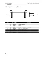
Страница 22: ...ptional Item Part Number Description 24930M Cylinder Complete X3913 Seal Kit F9117 Spout Deflector Cylinder Hose Kit 1 24930M 1 3 4 ID x 5 Stroke Cylinder 2 116984 Hose 3 8 x 120 c w Fittings 3 960913...

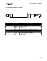
Страница 23: ...Item Part Number Description 25337M Cylinder Complete X3907 Seal Kit F0695 Hydraulic Cylinder Hose Kit for Spout Swivel 1 25337M 2 0 ID x 8 Hydraulic Cylinder 2 909985 Hose 3 8 x 78 1 2 MNPT x 9 16 M...

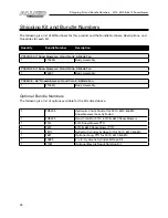
Страница 24: ...an 1 F0437 Body Assembly YC6610 4 66 Snowblower w Hand Crank 4 Blade Fan 1 F1542A Body Assembly Optional Bundle Numbers The following is a list of options available for the Kits listed above 1 FX9304...

Страница 25: ......

Страница 26: ...quire replacement as part of normal maintenance Also Buckets and Bucket Tines carry no warranty Bent Spears carry no warranty Snowblower Fan Shafts carry no warranty Mower Blades carry no warranty Por...

Страница 27: ...quests must be prepared on Buhler Industries Inc Warranty Claim Forms with all requested information properly completed Warranty Claims must be submitted within a thirty 30 day period from date of fai...

Страница 28: ...r enlarge this limited warranty or its exclusions limitations and reservations Corrections of defects and improper workmanship in the manner and for the applicable time periods provided for herein sha...

Страница 29: ......
Страница 30: ...tries Inc 1330 43rd Street NW Fargo ND USA 58102 Ph 701 282 7014 Fax 701 282 5865 Toll Free 888 524 1004 E mail info buhler com www farm king com Equipment shown is subject to change without notice 20...

Отзывы: