FARGO electronics HDP5000 dual-side Скачать руководство пользователя страница 82

RESTRICTED USE ONLY 


Fargo Electronics, Inc. 

HDP5000 High Definition Card Printer/Encoder User Guide (Rev. 1.4) 


4-6

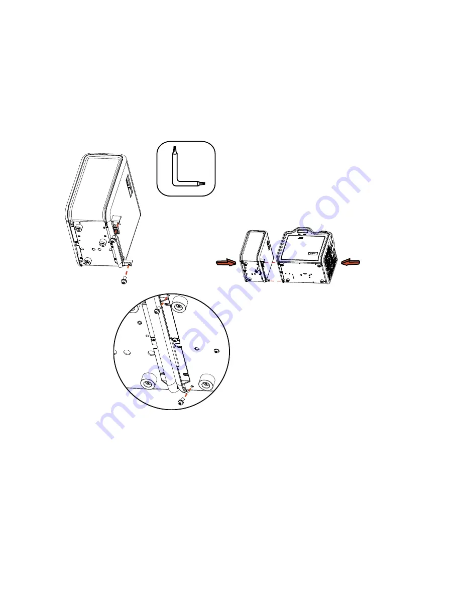
Flipper Module Accessory (continued) 

Display A - Slide the Flipper Module attachment tabs and the PCB-INTF Board into the 
appropriate slots at the base of Printer Module. This picture shows the Printer and the Flipper 
Module. 


Содержание HDP5000 dual-side

Страница 1: ...ide Rev 1 4 HDP5000 single side HDP5000 dual side HDP5000 single side with single side lamination HDP5000 dual side with single side lamination HDP5000 single side with dual side lamination HDP5000 dual side with dual side lamination Part Number L000950 ...

Страница 2: ...ference documents were thoroughly reviewed to provide Fargo with professional and international standards requirements guidelines and models for our technical training and User documentation At all times the Copyright Protection Notice for each document was adhered to within our Fargo documentation process This reference to other documents does indicate that Fargo is an ISO certified company at th...

Страница 3: ..._________________________ 2 20 Printer Components Blank Cards ___________________________________________________ 2 21 Printer Components Card Input and Output Hoppers____________________________________ 2 23 Printer Components Card Output Hopper and Reject Hopper _____________________________ 2 23 Printer Unit Reviewing the Card Lamination Module ___________________________________ 2 24 Printer C...

Страница 4: ...________________________________________ 5 44 Reviewing the Resin Self Test ______________________________________________________ 5 45 Section 6 Ethernet Option Section ___________________________________________6 1 Introduction________________________________________________________________________ 6 1 Technical Specification Ethernet Option ________________________________________________ 6 2 F...

Страница 5: ...e HDP5000 settings_____________________________________________________ 6 50 Changing the HDP5000 LCD Network Settings ________________________________________ 6 50 Accessing the Network Setup Menu__________________________________________________ 6 50 Changing the DHCP Setting________________________________________________________ 6 51 Changing the ANEG setting___________________________________...

Страница 6: ...______ 8 29 Using the Dual Sided Print Both Sides option _________________________________________ 8 30 Using the Print Both Sides Split 1 Set of Ribbon Panels option ___________________________ 8 31 Using the Print Both Sides Print Back Image on Front of Card option ______________________ 8 32 Using the Dual Sided Print Back Side Only option _____________________________________ 8 33 Using the Op...

Страница 7: ..._________ 8 100 Using the Printer Supplies tab _________________________________________________8 102 Reviewing Information on the Supplies tab ___________________________________________ 8 103 Section 9 Toolbox_________________________________________________________9 1 Accessing the Toolbox _______________________________________________________________ 9 1 Selecting the Configuration tab_______...

Страница 8: ...age _____________________________________ 9 31 Reviewing the Value outside the Range error message ___________________________________ 9 31 Section 10 Cleaning______________________________________________________10 1 Using the Required Supplies __________________________________________________________ 10 1 Safety Messages review carefully _____________________________________________________ 10 ...

Страница 9: ...onics Inc HDP5000 High Definition Card Printer Encoder User Guide Rev 1 4 ix Section 17 Glossary of Terms ______________________________________________17 1 Section 18 Index_________________________________________________________18 1 ...

Страница 10: ...u can go directly to the Glossary of Terms Technical Specifications and Functional Specifications to learn how to use the processes procedures functions and windows for the HDP5000 within concise correlative tables Table of Contents hyper linked You can use the automated Table of Contents to quickly locate for example an error message a procedure the index or an appendix Cross Referencing hyper li...

Страница 11: ...static electricity discharges Information that raises potential electrostatic safety issues is indicated by a warning symbol as shown to the left To prevent equipment or media damage refer to the following safety messages before performing an operation preceded by this symbol To prevent equipment or media damage observe all established Electrostatic Discharge ESD procedures while handling cables i...

Страница 12: ...on is returned from Headlift Sensor 5 The Print Ribbon moves forward until it finds the yellow panel pauses advances to magenta then backs up to yellow the Ribbon Sensor detects the color of the ribbon 6 The Transfer Film advances forward two panels from supply advances until the Print Film Sensor senses 2 marks on the Film 7 The Transfer Film advances forward one panel from supply advances until ...

Страница 13: ...er the Mag Head All stop 5 Stepper will turn ON in reverse direction and encode card All stop 6 Stepper will again turn on and position the trailing edge of the card under the Mag Head All stop 7 Stepper will turn ON in reverse direction and verify data encoded onto mag stripe 8 Stepper continues transporting card until the trailing edge is positioned under the Card Feed Position Sensor All stop 9...

Страница 14: ...ller The Card Feed Position Sensor determines card edge and number of steps to position card All stop 19 The Headlift Motor turns ON to raise the Transfer Roller and will stop when the Headlift Sensor is activated All stop 20 The Stepper and Film Drive engage to laminate the printed Film onto the card They will turn off after a given number of steps based on the position given by the card Sensor A...

Страница 15: ...wing the Lamination Module Boot up Sequence Step Process 1 The Lam Headlift turns until the head up position is returned from Headlift Sensor 2 The Lamination Ribbon Motor activates Note The RFID determine the presence of a roll of lamination 3 The Card Sensor checks for the presence of a card and ejects it if found ...

Страница 16: ...le 2 The card is fed to the Card Position Sensor 3 The Lamination Take up Motor begins cycling until the Lamination Sensor detects the mark 4 The Card Feed Motor activates to place the leading edge of the card on the Lam Roller 5 The Lam Roller Lift Motor cycles until the Transfer Roller Lift Sensor detects the roller is down 6 The Card Feed Motor and the Lamination Drive Motor activate for the le...

Страница 17: ...procedures unless otherwise specified Caution This device is electrostatically sensitive It may be damaged if exposed to static electricity discharges Information that raises potential electrostatic safety issues is indicated by a warning symbol as shown to the left To prevent equipment or media damage refer to the following safety messages before performing an operation preceded by this symbol To...

Страница 18: ... the HDP5000 Printer Overview table HDP5000 Series Input Hoppers Card Capacity Accepted Card Size Encoding Modules Lamination Module Flipper Table HDP5000 Single Sided Card Printer Enco der 1 100 100 per Cartridge CR 80 Optional Optional Optional HDP5000 LC Single Sided Card Printer Enco der 1 100 100 per Cartridge CR 80 Optional Included Optional HDP5000 Dual Sided Card Printer Enco der 1 100 100...

Страница 19: ...ser Guide Rev 1 4 2 3 Reviewing the HDP5000 Package These items are included with your HDP5000 Unpacking Instructions Software Installation CD includes Printer Driver Cleaning Roller One 1 power supply with Printer one 1 power supply with Laminator if purchased Reviewing the HDP5000 front ...

Страница 20: ...RESTRICTED USE ONLY Fargo Electronics Inc HDP5000 High Definition Card Printer Encoder User Guide Rev 1 4 2 4 Reviewing the HDP5000 Card Printer Display HDP5000 Printer with attached Output Hopper ...

Страница 21: ...d Printer complies with the requirements in Part 15 of the FCC rules for a Class A digital device UL The Card Printer is listed under UL IEC 60950 1 2001 INFORMATION TECHNOLOGY EQUIPMENT Note This product is intended to be supplied by a Listed Power Unit marked Class 2 and rated for 24 V dc 3 75 to 5 A File Number E145118 Agency Listings Term Description Emissions Standards CE FCC CRC c1374 EN 550...

Страница 22: ...the FCC Rules These limits are designed to provide reasonable protection against harmful interference when the equipment is operated in a commercial environment This equipment generates uses and can radiate radio frequency energy and if not installed and used in accordance with the instruction manual may cause harmful interference to radio communications Operation of this equipment in a residentia...

Страница 23: ...s Magnetic Stripe cards and Optical Memory Cards Card Cleaning Replaceable cleaning roller included with each print Ribbon Colors Up to 16 7 million colors and 256 shades per Pixel Input Card Cartridge Capacity HDP5000 and HDP5000 LC 100 cards 030in 762mm Has refillable Card Cartridge that can either be attached to the Printer or detached for storage This allows single feed with the Card Cartridge...

Страница 24: ...P5000 LC See Card tab under Printer Adjustments CR 80 This selection is the default form size for the HDP5000 This will print a 3 370 in L x 2 125 in W 85 6mm L x 54mm W image including a 04 over bleed on each of the 4 sides CR 80 default values Card Size supported is 2 204 X 3 452 56 X 87 7 mm Standard Card Size in inches HDP5000 Printer Driver Card tab Standard Card Size in mm HDP5000 Printer Dr...

Страница 25: ... null Print Length default 3 704 upper limit 3 704 lower limit 3 000 cannot be null Changing back to CR 80 resets to CR 80 defaults Custom Card Size in inches HDP5000 Printer Driver Card tab Custom Card Size in mm HDP5000 Printer Driver Card tab Card Size inches and mm Choice of inches or mm changes the counter choice on the K Panel Resin tab See below Inches displays card size in inches mm displa...

Страница 26: ...Sided Lam Module 12 75 H x 30 W x 9 25 D 324mmH x 762mmW x 235mmD Lam Module 12 75 H x 12 25 W x 9 25 D 324mmH x 313mmW x 235mmD Display User friendly SmartScreen LCD Control Panel Encoding Options only HDP5000 and HDP5000 LC ISO Magnetic Stripe Encoding Module dual high and low coercivity Tracks 1 2 and 3 JIS II Magnetic Stripe Encoding Module E card Docking Station required for all e card option...

Страница 27: ... void where not prohibited by law when non Fargo Certified Supplies are used HDP Film Options Clear 1 500 prints Standard Holographic 500 prints only HDP5000 and HDP5000 LC Custom Holographic special order 500 prints only HDP5000 and HDP5000 LC HDP Film Storage Temperature 77ºF 25ºC or lower for no longer than 1 5 years Humidity 20 to 80 non condensing Input Hopper Card Capacity HDP5000 and HDP500...

Страница 28: ...P5000 LC 200 cards 030mm Overlaminate Options HDP5000 LC and HDP5000 only All overlaminates are available in either clear holographic globe design or custom holographic design They can also be optimized for use with smart cards and Magnetic Stripes Here are the options Thermal Transfer Overlaminate 25 mil thick 500 prints PolyGuard Overlaminate 1 0 mil and 6 mil thick 250 prints PolyGuard availabl...

Страница 29: ... Batch Mode HDP5000 and HDP5000 LC see note below 38 seconds per card 95 cards per hour YMC with transfer 46 seconds per card 78 cards per hour YMCK with transfer 70 seconds per card 51 cards per hour YMCKK with transfer 70 seconds per card 51 cards per hour YMCFK with transfer 50 seconds per card 72 cards per hour YMCK with transfer and dual sided simultaneous lamination 75 seconds per card 48 ca...

Страница 30: ... 1 2 and 3 Contactless Smart Card Encoder HID iClass and MIFARE Contact Smart Card Encoder reads from and writes to all ISO7816 1 2 3 4 memory and microprocessor smart cards T 0 T 1 as well as synchronous cards Prox Card Reader HID read only Software Drivers Windows 2000 XP Server 2003 Supply Frequency 50 Hz 60 Hz Supply Voltage 100 240 VAC 3 8A HDP5000 and HDP5000 LC Supported Printers Models HDP...

Страница 31: ...ress U S only optional Extended Warranty Program U S only see below for more detail Two 2 Year Factory Warranty Covers parts and depot repair First year On Call Express loaner printer 2nd year On Call Express available for a fee This must be purchased before the first year On Call Express expires Extended Warranties available Printhead Lifetime unlimited pass with Fargo certified Cards Weight HDP5...

Страница 32: ...th of the Print Ribbon Panels The Printer always prints the yellow Panel first followed by the magenta Panel and the cyan Panel Printhead As the Print Ribbon passes beneath the Printhead hundreds of thermal elements within the Printhead heat the dyes on the Ribbon Note When these dyes are heated they vaporize and diffuse into the surface of the film and then the film is laminated onto the card sur...

Страница 33: ...rd Cartridge Load blank cards into this Cartridge Card Output Hopper Stores 200 cards Card Lamination Module Works in conjunction with the Printer to apply a variety of different overlaminates to printed cards providing increased card durability and security Note When printing a batch of cards the Printer can be encoding and printing one card while the Lamination Module laminates another card LCD ...

Страница 34: ... the Printer s current mode of operation Press the corresponding softkey button under the choice you want to select If no word appears above a particular button this indicates it has no function in that particular mode of operation LCD Display The Printer s LCD Display will change according to the Printer s current mode of operation Ready Printer Open Screens Once the Printer has finished its syst...

Страница 35: ...ta from the PC TRANSFERRING Indicates the Printer is transferring an image to a blank card LAM Indicates the Lamination Station is applying an overlaminate to a card appears only if using a Printer equipped with the optional Card Lamination Module The Print Status screen always displays Cancel in the lower left and Pause in the lower right The Cancel button Use this button to cancel print jobs and...

Страница 36: ... the resin thermal transfer print methods each provide their own unique benefits Print Ribbons are available in dye sublimation only and combination dye sublimation resin versions To make it easier to remember which Print Ribbons are which a letter code has been developed to indicate the type of Ribbon Panels found on each Ribbon This letter code is as follows Dye Sublimation Yellow Panel Dye Subl...

Страница 37: ... will print onto any card with a clean level and polished PVC surface Important Composite PVC is recommended over straight PVC for the best results and for ISO card specification compliance Single side straight PVC does not conform to ISO compliance at this time The Printer will print onto any card with a clean level and polished PVC surface Card Surface Suitable cards must have a polished PVC sur...

Страница 38: ...ilable and recommended for best results UltraCard stock has a glossy PVC laminate on top and bottom and is optically inspected to provide the cleanest most scratch and debris reduced cards possible Two types of these cards are available UltraCard and UltraCard III UltraCard stock has a PVC core and offers medium card durability Recommended UltraCard III stock has a 40 polyester core and offers hig...

Страница 39: ... Components Card Output Hopper and Reject Hopper Type Description Card Output Hopper HDP5000 HDP5000 LC All standard HDP Card Printers provide a 200 card capacity Card Output Hopper based on a standard 30 mil card thickness Note This Hopper stores the cards after they are printed Shown in the lower left Reject hopper functionality when connected to the Flipper Module The storage is available on th...

Страница 40: ...each temperatures exceeding 350 F 175 C Use extreme caution when operating the Laminator Never touch the Transfer Roller unless the Printer has been turned off for at least 20 to 30 minutes Select Printer models support the attachment of an optional Card Lamination Module This Module can be ordered pre installed on your Printer from the factory or can be ordered separately as a field upgradeable M...

Страница 41: ...ver setup window Once adjusted the new temperature settings will be sent down with the next print job along with the rest of the Printer Driver information New Temperature Setting Before printing begins the Transfer Roller will automatically adjust itself to the new temperature setting Note This new temperature setting will remain programmed within the Printer until it is once again changed within...

Страница 42: ...erlaminates Term Description Cross Reference Thermal Transfer Film and PolyGuard Overlaminates The Card Lamination Module will accept either a Thermal Transfer Film overlaminate or a Polyester Patch Overlaminate called PolyGuard Thermal Transfer Film The Thermal Transfer Film overlaminate is a relatively thin material which Covers a card Edge to Edge and provides a medium level of card durability ...

Страница 43: ...odate the CR 80 size See the Loading the Overlaminate Reviewing the Overlaminate Design Term Description Cross Reference Design Both PolyGuard and the Thermal Transfer Film overlaminates are available in either a clear or generic secure holographic type design Note Custom holographic type overlaminates are also available with specific designs patterns logos and security features Please contact the...

Страница 44: ...d if exposed to static electricity discharges Information that raises potential electrostatic safety issues is indicated by a warning symbol as shown to the left To prevent equipment or media damage refer to the following safety messages before performing an operation preceded by this symbol To prevent equipment or media damage observe all established Electrostatic Discharge ESD procedures while h...

Страница 45: ...to ensure that no damage has occurred during shipping Make sure that all supplied accessories are included with your unit Unpacking the Printer The following items are included with your Printer Software Installation CD includes Printer Driver Online User s Guide and Printer Diagnostic Tool Power Supply with Power Cord Note This product is intended to be supplied by a Listed Power Unit marked Clas...

Страница 46: ...RESTRICTED USE ONLY Fargo Electronics Inc HDP5000 High Definition Card Printer Encoder User Guide Rev 1 4 3 3 Unpacking the Printer continued Display A See the HDP5000 Printer Installation Guide ...

Страница 47: ...RESTRICTED USE ONLY Fargo Electronics Inc HDP5000 High Definition Card Printer Encoder User Guide Rev 1 4 3 4 Unpacking the Printer Display B See the HDP5000 Printer Installation Guide ...

Страница 48: ...he unit with its Covers open Do not install unit near heat sources such as radiators or air ducts or in a place subject to direct sunlight excessive dust mechanical vibration or shock About Moisture Condensation If the unit is brought directly from a cold to a warm location or is placed in a very damp room moisture may condense inside the unit Should this occur print quality may not be optimum Lea...

Страница 49: ...nters require highly specialized supplies to function properly To maximize Printer life reliability printed card quality and durability you must use only Fargo Certified Supplies For this reason your Fargo warranty is void where not prohibited by law if you use non Fargo Certified Supplies Step Procedure 1 Load the Print Ribbon into the Print Ribbon Cartridge until the Rolls click ...

Страница 50: ...RESTRICTED USE ONLY Fargo Electronics Inc HDP5000 High Definition Card Printer Encoder User Guide Rev 1 4 3 7 Loading the Print Ribbon continued Step Procedure 2 Tighten the Print Ribbon ...

Страница 51: ...E ONLY Fargo Electronics Inc HDP5000 High Definition Card Printer Encoder User Guide Rev 1 4 3 8 Loading the Print Ribbon continued Step Procedure 3 Insert the Print Ribbon Cartridge into the Printer until it clicks ...

Страница 52: ... ONLY Fargo Electronics Inc HDP5000 High Definition Card Printer Encoder User Guide Rev 1 4 3 9 Loading the Clear HDP Transfer Film Step Procedure 1 Load the HDP Film into the HDP Film Cartridge until the rolls click ...

Страница 53: ...RESTRICTED USE ONLY Fargo Electronics Inc HDP5000 High Definition Card Printer Encoder User Guide Rev 1 4 3 10 Loading the Clear HDP Transfer Film continued Step Procedure 2 Tighten the HDP Film ...

Страница 54: ...LY Fargo Electronics Inc HDP5000 High Definition Card Printer Encoder User Guide Rev 1 4 3 11 Loading the Clear HDP Transfer Film continued Step Procedure 3 Insert the HDP Film Cartridge into the Printer until it clicks ...

Страница 55: ...High Definition Card Printer Encoder User Guide Rev 1 4 3 12 Inserting the Card Cleaning Roller Step Procedure 1 Remove the Card Cleaning Roller from the Print Ribbon packaging and insert the Cleaning Roller onto the black spindle from the supply pack ...

Страница 56: ...ONLY Fargo Electronics Inc HDP5000 High Definition Card Printer Encoder User Guide Rev 1 4 3 13 Inserting the Card Cleaning Roller continued Step Procedure 2 Remove the protective sleeve from the Card Cleaning Roller ...

Страница 57: ... ONLY Fargo Electronics Inc HDP5000 High Definition Card Printer Encoder User Guide Rev 1 4 3 14 Inserting the Card Cleaning Roller continued Step Procedure 3 Insert the Card Cleaning Roller into the card input area ...

Страница 58: ...re only applies to the HDP5000 LC The loading process for both the Thermal Transfer Overlaminate and the PolyGuard Overlaminate material is the same Refer to the following steps to load either type of overlaminate into the Printer Step Procedure 1 Remove the overlaminate from its packaging 2 Load the Lamination Rolls into the Cartridges until they click ...

Страница 59: ...cs Inc HDP5000 High Definition Card Printer Encoder User Guide Rev 1 4 3 16 Loading the Overlaminate continued Step Procedure 3 Tighten the Lamination Rolls 4 Insert the Overlaminate Cartridges into the Lamination Module until they click ...

Страница 60: ...RESTRICTED USE ONLY Fargo Electronics Inc HDP5000 High Definition Card Printer Encoder User Guide Rev 1 4 3 17 Loading the Overlaminate continued Step Procedure 5 Close the Lamination Module Front Cover ...

Страница 61: ...oder User Guide Rev 1 4 3 18 Loading the Blank Cards Step Procedure 1 Load the blank cards into the Card Cartridge as shown below Important The front of the card must face DOWN The back of the card or the magnetic stripe on the card must face UP The Smart Chip is loaded on the bottom ...

Страница 62: ...SE ONLY Fargo Electronics Inc HDP5000 High Definition Card Printer Encoder User Guide Rev 1 4 3 19 Loading the Blank Cards continued Step Procedure 2 Place the Card Input Cartridge onto the Printer until it clicks ...

Страница 63: ...across the USB connection Do not plug in the USB cable until prompted to do so during the installation of the HDP5000 Printer Driver See the Installing the Printer Driver on Windows XP and Windows 2000 procedure Step Procedure 1 The Printer connections are shown in the Displays A to D 2 Use the same procedure for both the Printer and the Lamination Module Display A Connecting the AC power cable to...

Страница 64: ...Connecting the other end of the AC power cable to a Surge Protector See both notes below Note No 1 Instead of connecting the AC power cable directly into an AC outlet it is recommended that a Surge Protector be used to protect against power surges Note No 2 Some buildings have surge protection built into the electrical outlets Please consult your building supervisor regarding this feature ...

Страница 65: ...r Guide Rev 1 4 3 22 Connecting Power to HDP5000 Printer and Lamination Module continued Display C Connecting the plug from the power supply to the Printer as shown below Display D Connecting the plug from the power supply to the Lamination Module as shown below The Printer must be attached ...

Страница 66: ...ocedure 1 Close down all programs and insert the Software Installation CD into your computer s CD drive After a few seconds the CD s installer program will automatically open Follow the CD s on screen Procedures to complete installation Note If the CD does not automatically open use My Computer or Windows Explorer to view the contents of the CD Then double click on the Setup exe file listed on the...

Страница 67: ...NLY Fargo Electronics Inc HDP5000 High Definition Card Printer Encoder User Guide Rev 1 4 3 24 Installing the HDP5000 Printer Driver continued Step Procedure 2 Click on the Next button to continue with the installation ...

Страница 68: ...on Card Printer Encoder User Guide Rev 1 4 3 25 Installing the HDP5000 Printer Driver continued Step Procedure 3 a Read the License Agreement Select the I accept the terms of the license agreement option b Click on the Next button to continue with the installation ...

Страница 69: ... Inc HDP5000 High Definition Card Printer Encoder User Guide Rev 1 4 3 26 Installing the HDP5000 Printer Driver continued Step Procedure 4 a Select Local to install a USB Printer OR b Select Network and enter an IP Address for the Printer ...

Страница 70: ...SE ONLY Fargo Electronics Inc HDP5000 High Definition Card Printer Encoder User Guide Rev 1 4 3 27 Installing the HDP5000 Printer Driver continued Step Procedure 5 Click on the Next button to begin the installation ...

Страница 71: ...ESTRICTED USE ONLY Fargo Electronics Inc HDP5000 High Definition Card Printer Encoder User Guide Rev 1 4 3 28 Installing the HDP5000 Printer Driver continued Step Procedure 6 Wait during the installation ...

Страница 72: ...ronics Inc HDP5000 High Definition Card Printer Encoder User Guide Rev 1 4 3 29 Installing the HDP5000 Printer Driver continued Step Procedure 7 Applies to USB Printer installation Connect the USB cable to both the PC and the Printer ...

Страница 73: ...ng the HDP5000 Printer Driver continued Step Procedure 8 Applies to USB Printer installation a Select the Printer Port Note You have the option of selecting the port only IF you click the BACK button from the previous screen shot otherwise this is automatic b Wait while the Driver components are being copied to your PC ...

Страница 74: ...ctronics Inc HDP5000 High Definition Card Printer Encoder User Guide Rev 1 4 3 31 Installing the HDP5000 Printer Driver continued Step Procedure 9 Click the Finish button 10 Reboot your computer 11 You have completed this procedure ...

Страница 75: ...puter s startup menu select Settings Printers and Faxes Windows XP or Printers Windows 2000 b Double click on the HDP5000 Card Printer under the Printer s window c Select Printing Preferences under the Printer drop down menu Note This will bring up the HDP5000 Printing Preferences window 3 a Select the Card tab and then click on the Test Print button as shown in Display A on the next page b When t...

Страница 76: ...go Electronics Inc HDP5000 High Definition Card Printer Encoder User Guide Rev 1 4 3 33 Printing a Test Print Image continued Step Procedure 4 This completes the HDP5000 High Definition Card Printer Encoder Installation Guide ...

Страница 77: ... if exposed to static electricity discharges Information that raises potential electrostatic safety issues is indicated by a warning symbol as shown to the left To prevent equipment or media damage refer to the following safety messages before performing an operation preceded by this symbol To prevent equipment or media damage observe all established Electrostatic Discharge ESD procedures while ha...

Страница 78: ...ics Inc HDP5000 High Definition Card Printer Encoder User Guide Rev 1 4 4 2 Using the Security Lock Slot on the HDP5000 Important Compatible locks are not sold by Fargo Electronics however they are readily available from computer stores ...

Страница 79: ...ock To prevent unauthorized removal of the HDP5000 attach an industry standard security cable to an immovable object and then lock the cable to the Security Lock Slot Note Fargo does not sell any type of locking device but provides this feature for your added security The lock slot has a plastic covering that needs to be penetrated by the lock Note Simply push the lock end into the slot with adequ...

Страница 80: ... Tools needed Press the Release tab with a flat blade Use the Snap and Clip process Estimated Repair Time 1 minute Step Procedure 1 Caution Power off the Printer by unplugging the power cord from the Printer 2 Press the release tab in back while simultaneously pulling at the center of the bottom edge 3 Reverse instructions to re assemble Leave it off if your printer is upgraded for the Flipper or ...

Страница 81: ...t the output side of the Printer If there is a Lamination Module attached the Flipper Module is placed in between the Printer and Lamination Module 4 a Remove the Output Side Upgrade Cover D910139 01 b Release the latch on the upgrade cover c Pull on the bottom of the upgrade cover to remove it from the printer 5 a Turn the Printer and the Flipper Module on their back b Use the Torx tool provided ...

Страница 82: ...n Card Printer Encoder User Guide Rev 1 4 4 6 Flipper Module Accessory continued Display A Slide the Flipper Module attachment tabs and the PCB INTF Board into the appropriate slots at the base of Printer Module This picture shows the Printer and the Flipper Module ...

Страница 83: ...e of the Flipper Module OR If there is no Flipper Module it is installed at the output side of the Printer Remove the Card Output Hopper 4 a Remove the Output Side Upgrade Cover D910139 01 b Release the latch on the Upgrade Cover c Pull on the bottom of the Upgrade Cover to remove it from the printer 5 a Turn the Printer and the Flipper Module on their back b Use the Torx tool provided to remove t...

Страница 84: ...r Guide Rev 1 4 4 8 Installing the Lamination Module Accessory continued Display Slide the Lamination Module attachment tabs and the PCB INTF Board into the appropriate slots at the base of Printer or Flipper Module This picture shows the Printer the Flipper Module and the Lamination Module ...

Страница 85: ...bons to function properly To maximize Printer life reliability printed card quality and durability you must use only Fargo Certified Supplies For this reason your Fargo warranty is void where not prohibited by law if you use non Fargo Certified Supplies To order additional materials please contact your authorized reseller LCD Messages The LCD display shows the current status of the Printer Refer t...

Страница 86: ...static electricity discharges Information that raises potential electrostatic safety issues is indicated by a warning symbol as shown to the left To prevent equipment or media damage refer to the following safety messages before performing an operation preceded by this symbol To prevent equipment or media damage observe all established Electrostatic Discharge ESD procedures while handling cables i...

Страница 87: ... a 3 column presentation to present a specific LCD or Printer error message its cause and its solution This allows the troubleshooter to identify the error and its cause and then perform the procedure provided in the solution column This standard mode of identifying the problem and its solution should provide an efficient method of troubleshooting this printer If you encounter problems beyond the ...

Страница 88: ...d the PC Error Message window below This allows you to correlate the LCD Error Message with the PC Error Message identifying number then troubleshoot your Printer as needed Display Single Example from the LCD Error Message Table LCD Error Message Cause Solution Unable to Feed Card PC Error Message Nos 14 and 81 Matches with the screenshot below The Printer is unable to feed a card from the Card Ca...

Страница 89: ...nsors need to be calibrated Select Cancel and then perform the Film calibration procedure Calibrate Ribbon PC Error Message Nos 128 and 170 The print Ribbon Sensor is out of calibration Select Cancel and then perform the Ribbon calibration procedure Card Feed Stop PC Error Message No 137 The Front Cover was opened This caused the card transfer to stop OR the pause button was selected Press Resume ...

Страница 90: ...PC Error Message No 244 The film is not able to move correctly Check for jams breaks Check for obstruction If the problem persists call for technical assistance Check Laminate 1 PC Error Message Nos 213 and 231 The Laminator was unable to find the mark on the material in Cartridge 1 Make sure there are no obstructions to the Sensor and recalibrate the Laminator Sensor Check Laminate 2 PC Error Mes...

Страница 91: ...ts call for technical assistance E Card Startup Error PC Error Message No 141 A problem was detected during Printer start up Reset the Printer and try again If this problem persists call for technical assistance EEPROM Corrupt PC Error Message Nos 38 39 40 and 144 EEPROM restored with factory default values If changes were made then go into the setting values and reset these numbers Ejecting Card ...

Страница 92: ...t the Printer and try again If this problem persists call for technical assistance Film Align Error PC Error Message Nos 26 and 176 The film is not able to move correctly Check for jams breaks Check for obstruction If the problem persists call for technical assistance Film Break Jam PC Error Message No 158 The film is not able to move correctly Check for jams breaks Check for obstruction If the pr...

Страница 93: ...lipping area of the Printer Open the Printer s Flipping Module Cover Clear any cards in the Flipping Module by opening the Printers Cover and using the Forward and or Back buttons located on the Printer s Front Cover Ensure that the Flipper Module can rotate freely Close the Printer s Flipping Module Cover Press the Resume button on the Printer s Front Cover to continue printing To cancel the prin...

Страница 94: ...inthead Temperature Sensor is not functioning or is not connected properly OR The Printhead is not cooling properly If the problem persists call for technical assistance Head Voltage Err PC Error Message Nos 103 and 105 A hardware fault has prevented setting the correct Printhead voltage Reset the Printer and try again If this problem persists call for technical assistance Headlift Error PC Error ...

Страница 95: ...No 93 An unauthorized Ribbon is installed in the Printer Get the correct Ribbon from your dealer Job Data Error PC Error Message No 106 The print data sent to the Printer is corrupt or has been interrupted Reset the Printer and try again If this problem persists call for technical assistance Lam 1 Tag Err PC Error Message No 259 A RFID read or write error occurred on Cartridge 1 Retry and if it fa...

Страница 96: ...r the obstruction Lam Com Error PC Error Message No 246 There was a communication failure between the Printer and Laminator Check Lam power connections and restart the Printer Lam Error PC Error Message Nos 237 and 238 52 A generic unknown error as occurred Reset the Printer and try again If this problem persists call for technical assistance Lam Card Not Ejected PC Error Message No 216 The card i...

Страница 97: ...ror Message No 157 There is no material loaded in the Laminator Load Laminator material Lam Timeout PC Error Message No 247 The Printer timed out while processing information related to the Laminator Check Lam power connections and restart the Printer Lam1 Wrong Film PC Error Message No 233 Material in Cartridge 1 of the Laminator does not match the material type specified by the job Make sure Dri...

Страница 98: ...en it runs out Laminate 1 Out PC Error Message No 208 The Laminate in Cartridge 1 has run out Replace it with a new roll of material Laminate 2 Bad PC Error Message No 260 and 262 The Lamination material in Cartridge 2 is not valid for this Laminator Install valid material Laminate 2 Jam PC Error Message No 230 A Jam occurred with the Laminator material in Cartridge 2 Open Lam cover and clear the ...

Страница 99: ... or sense the upper Lam Module 2 head Check head connections call for service repair Mag Encoder Paused PC Error Message No 143 The Magnetic Encoder is in a pause state Mag Encoder Startup Error PC Error Message No 63 and 141 A problem was detected during Printer start up Reset the Printer and try again If this problem persists call for technical assistance Mag Verify Error PC Error Message No 30 ...

Страница 100: ...nstall the Film and press Resume To cancel the print press the Cancel Print button or the Cancel button located on the Printer No Flip Module PC Error Message No 201 Two sided job sent to a one sided Printer Verify the Printer has flipper capabilities via the LCD Menu If Flipper capabilities are present ensure that the Print Both Sides option in the Driver is set correctly Press the Resume button ...

Страница 101: ... send encoding data but the Printer is not configured with this Encoder type No MiFare Encoder PC Error Message No 203 You are trying to send encoding data but the Printer is not configured with this Encoder type To cancel click on Cancel Print No Prox Encoder PC Error Message No 32 You are trying to send encoding data but the Printer is not configured with this Encoder type To cancel click on Can...

Страница 102: ...echnical assistance Reboot Required PC Error Message Nos 9 65 67 and 163 Unspecified system error detected by the Printer Firmware Reset the Printer and try again If this problem persists call for technical assistance Reinsert Ribbon PC Error Message No 141 The Ribbon must be reinserted for proper functioning of the Printer Reinsert the Ribbon or press Resume Remove Card PC Error Message No 68 A c...

Страница 103: ...aded in the Lam 1 Module Remove Cartridge 1 Remove Lam2 Mtl PC Error Message No 205 Single sided lamination on the front side is specified but material is loaded in the Lam 2 Module Remove Cartridge 2 Ribbon Break Jam PC Error Message No 99 108 and 109 The Ribbon is not able to find the next panel correctly Check for jams breaks If jammed clear the jam If broken repair by taping the Ribbon back on...

Страница 104: ...e print Ribbon has run out Install a new Ribbon and press Resume to continue Ribbon Tension PC Error Message No 98 The Ribbon tensions may be out of range Check and adjust the setting through the TOOLBOX under the Advanced Settings tab If this problem persists call for technical assistance Press Resume to continue or cancel to abort Ribbon Wrong Material PC Error Message No 93 122 and 172 The prin...

Страница 105: ...ors Waiting for Data PC Error Message No 147 The Printer has stopped receiving data from the PC Reset the Printer and try again If this problem persists call for technical assistance Wrong Film PC Error Message Nos 162 and 163 The print film installed in the Printer does not match the film type selected in the Printer Driver OR A Self test job cannot be printed with the print media installed Repla...

Страница 106: ...remove the card and cancel the print by pressing the Cancel Print button from the Driver s display dialog or the Cancel button located on the Printer Cover is Open The Printer cannot start printing because the Cover is open Close the Cover to continue printing Unable to Feed The Printer is unable to feed a card from the Card Cartridge Ensure that cards are available and loaded correctly press the ...

Страница 107: ...D display to continue printing e To Cancel the print press the Cancel Print button from the Driver s display dialog and the Cancel button located on the Printer s LCD display Card Jam Encoder A Card has become jammed in the Printer s Encoding station a Open the Printer s Front Cover and remove the Print Ribbon b Open the Printer s Flipping Module Cover c Clear any cards in the Encoding Module by u...

Страница 108: ... To cancel the print press the Cancel Print button from the Driver s display dialog or the Cancel button on the Printer s LCD display Card Jam Laminator A Card has become jammed in the Printer s Lamination Module a Open the Printer s Module s Front Cover and remove the Overlaminates b Clear any cards in the Lamination Module by using the Forward Arrow and or Back Arrow buttons located on the Print...

Страница 109: ...rint press the Cancel Print button from the Driver s display dialog or the Cancel button located on the Printer s LCD display Flipper Jam The Flipper Table has jammed while either aligning itself or flipping a card a Open the Printer s Flipper Module Cover b Clear any cards in the Flipper Module by using the Forward and or Back buttons located on the Printer s Front Cover c Ensure that the Flipper...

Страница 110: ...ancel Print button from the Driver s display dialog or press the Cancel button located on the Printer s LCD display Ribbon RFID Error The ribbon tag information is corrupted or incorrect Check that the Ribbon is installed properly Cancel is the only option Press the Cancel Print button from the Driver s display dialog or the Cancel button located on the Printer s LCD display Wrong Ribbon Installed...

Страница 111: ...with the Printer Error Message Table continued Printer Error Message Cause Solution No Ribbon Installed No Print Ribbon is installed in the Printer Install the correct Ribbon and press Resume on the LCD display Ribbon Out The Print Ribbon installed in the printer is empty Install a new Ribbon and press Resume on the LCD display ...

Страница 112: ... Back buttons located on the Printer s LCD display c Tape the ends of the Ribbon together and wind any excess onto the Take up Spool of the Print Ribbon d Re install the Print Ribbon close the Printer Cover and press the Resume button located on the Printer s LCD display to continue printing e To cancel the print press the Cancel Print button from the Driver s display dialog and the Cancel button ...

Страница 113: ... in a SecureMark Printer a Replace with the appropriate SecureMark Ribbon and press the Resume button located on the Printer s LCD display to continue printing b To cancel the print press the Cancel Print button from the Driver s display dialog and the Cancel button located on the Printer s LCD display c Install a Certified Print Ribbon and press the Resume button located on the Printer s LCD disp...

Страница 114: ...ton located on the Printer s LCD display to continue printing To cancel the print press the Cancel Print button from the Driver s display dialog and the Cancel button located on the Printer s LCD display Invalid Ribbon An incorrect Print Ribbon has been installed in the Printer Check that the ribbon is correct for the printer and retry To cancel click on Cancel Print Ribbon Error The Print Ribbon ...

Страница 115: ...data Check the Cards and click on Cancel Print No Mag Strip Present The Printer is unable to find a Magnetic stripe on the card Check the Cards and click on Cancel Print No Smart Card Encoder No Smart Card Encoder is installed in the printer To cancel click on Cancel Print No Prox Card Encoder No Proximity Card Encoder is installed in the printer To cancel click on Cancel Print Headlift Error The ...

Страница 116: ...nnected cycle power and press the Resume button to continue To cancel press the Cancel Print button or the Cancel button located on the Printer Laminator Heater Off The Laminator s Heater is OFF Press the Resume button to continue To cancel press the Cancel Print button or the Cancel button located on the Printer Laminator Heater Timed Out The Laminator cannot reach the desired operating temperatu...

Страница 117: ...s installed To cancel the print press the Cancel Print button or the Cancel button located on the Printer Wrong Laminator Film Installed An incorrect laminator film has been installed or a driver setting is incorrect Ensure that the appropriate Laminator Film is installed and press the Resume button located on the Printer to continue printing To cancel press the Cancel Print button or the Cancel b...

Страница 118: ...e Printer s LCD display c Tape the ends of the overlaminate together and wind any excess onto the Take up Spool of the Overlaminate d Re install the Laminator Cartridge s close the Laminator Cover and press the Resume button located on the Printer s LCD display to continue printing e To cancel the print press the Cancel Print button from the Driver s display dialog and the Cancel button located on...

Страница 119: ...n the Printer Install the Film and press Resume To cancel the print press the Cancel Print button or the Cancel button located on the Printer Print Film Sensor Error The Printer cannot find the next panel on the Print Film Check that the Print Film is installed properly and press Resume To cancel the print press the Cancel Print button or the Cancel button located on the Printer Wrong Print Film I...

Страница 120: ...nter A non SecureMark Film is installed in a SecureMark Printer Replace with the appropriate SecureMark Film and press the Resume button on the Printer to continue printing To cancel press the Cancel Print button or the Cancel button on the Printer Print Film Error The Print Film caused a general error Ensure that the appropriate Print Film is installed and press the Resume button located on the P...

Страница 121: ...igher USB Port Optional Ethernet connection 2 Confirm the correct installation of the Printer Driver a Close the software program and check the Printer Driver b Reboot the computer c Ensure the Printer Driver is installed correctly Note This pertains especially if an obsolete Driver was recently removed d Ensure the correct setup options within the Printer Driver are selected e Confirm that the Dr...

Страница 122: ...p 2 Click on the Printer button and select the HDP5000 Card Printer 3 Click OK and reset all four margins to zero Note The WordPad will automatically replace the values with its minimum margins 4 Open the program and type This is a Test then go to File on the menu bar and select Print 5 Determine whether there is adequate hard Drive space Note A large volume of temporary files on the computer can ...

Страница 123: ...ng a Test Image Step Procedure 1 Open the Diagnostic Tool from the Driver Choose Run Tests to select a preset test image Select Self Tests Note These images help to determine if the Printer is functioning properly 2 Scroll to the desired Self Test image from the Choose Test window options and press the Run Test button ...

Страница 124: ...gnment Self Test Card Step Procedure 1 Use this card to determine Image Placement and confirm that the Printer is working properly Note The image consists of sixteen 16 gray scale boxes and alignment arrows The gray boxes are composed from a composite of YMC color panels Adjust the TOF and EOF settings to change image placement ...

Страница 125: ...uide Rev 1 4 5 41 Reviewing the Color Bars Self Test Step Procedure 1 Use this card to confirm that image colors are properly reproduced Image consists of sixteen graduated steps of RGB and YMCK Note This print will provide maximum image size giving complete card Coverage on a CR 80 sized card ...

Страница 126: ... Printer Encoder User Guide Rev 1 4 5 42 Reviewing the Device Settings Self Test Step Procedure 1 Use this card to view the Printer settings and counts for Card Count CC Card Cleaning Count TC and others The Card Count is the total number of cards the Printer has produced ...

Страница 127: ...r Guide Rev 1 4 5 43 Reviewing the YMCK Self Test Step Procedure 1 Use this card to confirm that image colors are properly reproduced Image consists of sixteen graduated steps of RGB and YMCK Note This print will provide maximum image size giving complete card Coverage on a CR 80 sized card ...

Страница 128: ...oder User Guide Rev 1 4 5 44 Reviewing the Magnetic Self Test Step Procedure 1 This option only applies if a Magnetic Encoding Module is installed in the Printer Note The Printer will feed encode and eject a card Be sure to have high coercivity cards installed when running this test ...

Страница 129: ...SE ONLY Fargo Electronics Inc HDP5000 High Definition Card Printer Encoder User Guide Rev 1 4 5 45 Reviewing the Resin Self Test Step Procedure 1 Use this card to determine that the Resin Panel is printing properly ...

Страница 130: ...you can monitor and manage the Printer just as you would any other networked Printer Compatibility The Fargo Ethernet option provides compatibility with TCP IP and 802 3 Ethernet protocols with an IEEE 802 3 10 100Base T Ethernet female RJ45 connector Application The Ethernet Option applies to the Fargo HDP5000 High Definition Card Printer Encoder With the Ethernet Option properly installed and co...

Страница 131: ...hernet option installed is required Printer Configuration Since TCP IP is used for the network communication the Printer must be configured with an IP address and a subnet mask before it can be seen on the network An additional network setting for the Default Gateway can also be configured which allows communication across the subnets Host Computer A PC running Windows 2000 Windows XP Windows 2003...

Страница 132: ...nfiguration with any web browser Log Messages Provides logging of usage and error events via e mail UDP or TCP IP Password Security Provides security with passwords and configurable User permission levels Telnet Provides a Telnet command line interpreter for Printer configuration SNMP Provides an SNMP agent that supports MIB II Upgrades Provides support for Firmware upgrades over the network Troub...

Страница 133: ...ther or not a print job has been successful Also the User knows what problems have been encountered while processing the print job Printing using Ethernet works in a manner similar to the USB connected PC Printer Reviewing the Web Page Server An HTTP service serves web pages that provide an interface through which to configure and monitor the Printer Note Users may also monitor all print jobs that...

Страница 134: ...cedure shows how to initiate a Telnet session from a PC in order to access the Telnet services provided by the Printer Description Initiating a Telnet session Follow these instructions to issue Telnet commands 1 Identify the IP address of your Printer Note See Switching to the Automatic IP Address Mode 2 Initiate a Telnet session from a DOS window on your PC At the DOS prompt enter telnet IP Addre...

Страница 135: ...rtial full word commands the Printer will respond with additional help For example you can enter list and the Printer will respond with all subcommands to the list command Telnet Command Command Purpose Command Format help Display help for Telnet commands reset Reset the Ethernet interface for the HDP5000 Printer Encoder reset ping Send a ping command to another IP address as a test of the Etherne...

Страница 136: ...lay information about the Printer i e model label contact location Firmware version and date and serial number list sysinfo ribbon Display information about the installed Ribbon in the Printer list ribbon net Display information about the current network settings of the Ethernet interface list net stored net Display information about the stored network settings of the Ethernet interface list store...

Страница 137: ...nd Table continued Telnet Command Command Purpose Command Format lpq Display information about print jobs and their settings list lpq Printer Display information about the Printer i e model number Firmware version and serial number list Printer Printer sm Display information about the secure mark settings of the Printer list Printer sm ...

Страница 138: ...of a system log path set syslog LOG_NAME name NEW_NAME type Change the type of a system log path This starts or stops logging on start of jobs or on faults set syslog LOG_NAME type job pfault dest Change the destination of a system log path This may be set to none e mail udp or tcp set syslog LOG_NAME dest none email udp tcp email Change the e mail address for e mail notification for a system log ...

Страница 139: ...tion The HDP5000 allows only two 2 User definitions set User add NAME del Delete a User definition set User del NAME passwd Define a new password for a User set User passwd NAME PASSWORD type Specify a User as root or guest Only root Users have administrative rights to change network interface settings set User type NAME root guest set User from Restore User setting from default or stored settings...

Страница 140: ... disable automatic address assignment using DHCP Static non automatic addresses will come from the stored or default settings depending on the other settings To enable automatic address assignment store net opts dhcp To disable automatic address assignment store net opts dhcp net from Restore the network settings from either the default settings or the current settings store net from default curre...

Страница 141: ...Display information about the Printer status This includes the status and device response See the Printer web page description lpstat cancel Cancel a specific print job from the print queue cancel 10 quit Stop the current Telnet session quit Ethernet Web Pages Standard Procedures Reviewing Web page security You can use the web pages from your Fargo Ethernet connected Printer to view several attrib...

Страница 142: ...ault administrative User name is root The default non administrative User name is guest Non administrative Users can only view settings 2 Enter the correct password The default password is an empty string If the password has not been changed leave the field blank See Password page procedure for changing passwords 3 Press Enter or click on the OK button 4 If the name and password is not accepted an...

Страница 143: ...ess of the Printer Note See Accessing the HDP5000 IP Address as needed to get this from the LCD of the Printer 3 Enter the IP address of the Printer you want to access into the address bar of the browser Note The IP address will change for your printer installation 4 Press Enter or click on GO 5 View the Home page The Home Page displays general information about the Printer See the next page Displ...

Страница 144: ...RESTRICTED USE ONLY Fargo Electronics Inc HDP5000 High Definition Card Printer Encoder User Guide Rev 1 4 6 15 Reviewing the Home Page This section provides a display of the HDP5000 Home Page ...

Страница 145: ...s the label that the User assigns to the Printer This label is reported to the DHCP server as the Host Name that may be used by the DNS server to resolve the IP address of the Printer If left blank the Printer will use a unique label based on the MAC address of the Printer Location Indicates the location string that the User assigns to the Printer Set by User May be configured via Telnet or from t...

Страница 146: ...ring the Network Settings The procedures needed to configure the network settings are presented in this section Accessing the Network Settings page The Network page displays the current network settings and allows the User to change the settings Step Procedure 1 Select the Network link from any web page of the Printer ...

Страница 147: ...pported by the Printer Reviewing the Current Settings The Current Settings page section displays the current active network settings for the Printer These are also labeled as Dynamic if they were provided by DHCP or Static if they came from the Stored Settings The current settings will be Dynamic only if Obtain an IP address automatically was selected when the Printer was restarted last ...

Страница 148: ...cally radio button to enable the DHCP BOOTP which automatically assigns the network settings Even with this button selected the User can enter Stored Settings and the Stored Settings will remain in memory See below Note This is the default method 3 Click on the Submit button to save this setting 4 Login as a root User if you are so prompted Note Any change of setting will only be accepted after yo...

Страница 149: ...d for Ethernet communications from within the same subnet With only these entries the User will be unable to print from a subnet other than the subnet on which the Printer is connected These required settings are the following IP Address Subnet Mask 4 Enter the optional network settings for Ethernet communications across a router from other subnets as follows Default Gateway 5 Enter the optional n...

Страница 150: ... Rev 1 4 6 21 Changing to the static IP address mode continued Step Procedure 7 Login as a root User if you are so prompted Note Any change of setting will only be accepted after you have successfully logged in 8 Reboot the Printer to effect this change See the Reviewing Web page security procedure ...

Страница 151: ...High Definition Card Printer Encoder User Guide Rev 1 4 6 22 Using the Clear Changes button Step Procedure 1 Click on the Clear Changes button to delete the information in the textboxes in Stored Settings area See the lower left corner of this display ...

Страница 152: ...age This page displays Media information about the Ribbon and Film currently installed in the Printer Step Procedure 1 Select the Status link from any web page of the Printer 2 Select the Media page link 3 View currently installed Ribbon information pertaining to the following Part Number SecureMark Part Number Percent Remaining Ribbon Type ...

Страница 153: ...CP IP page displays the TCP IP Status of each Printer connection which are not configurable See the next two pages for displays Step Procedure 1 Select the Status link from any web page of the Printer 2 Select the TCP IP page link 3 View information on all current network connections in the TCP connections area Continued on the next page ...

Страница 154: ...RESTRICTED USE ONLY Fargo Electronics Inc HDP5000 High Definition Card Printer Encoder User Guide Rev 1 4 6 25 Using the TCP IP page See the Using the TCP IP page procedure ...

Страница 155: ...eing sent to the Printer printing waiting Indicates that the communication is being slowed by print operations printing blocked Indicates that the communication has been stopped by some condition status canceled Indicates that the current job was canceled and is being rerouted online Indicates it is ready to print offline Indicates that the Cover is open or the Printer is not ready to print Printe...

Страница 156: ...RESTRICTED USE ONLY Fargo Electronics Inc HDP5000 High Definition Card Printer Encoder User Guide Rev 1 4 6 27 Reviewing the Printer page continued See the previous page for descriptions of the fields ...

Страница 157: ...finition Card Printer Encoder User Guide Rev 1 4 6 28 Using the System Log page The System Log page displays the current system log settings and allows the User to change the settings Note These settings configure how system logging occurs There are two logs ...

Страница 158: ... updates the link to the corresponding web page Step Procedure 1 Select the System Log link 2 Select the link for the log name you want to view or configure the default choices are log1 or log2 See the previous page 3 Enter a new log name in textbox 4 Click on the Submit button to save this change 5 Login as a root User if you are so prompted Note Any change of setting will only be accepted after ...

Страница 159: ...he log name you want to view or configure the default choices are log1 or log2 3 Select the Print Job Started checkbox to generate the log entries for each Print Job Started 4 Select the Printer Error checkbox to generate the log entries for each Printer Error 5 Select the Submit button 6 Login as a root User if you are so prompted Note Any change of setting will only be accepted after you have su...

Страница 160: ... Procedure No event logging 1 Select the System Log link 2 Select the link for the log name you want to view or configure the default choices are log1 or log2 3 Select the None radio button when no log is required Note This is the default 4 Select Submit 5 Login as a root User if you are so prompted Any change of setting will only be accepted after you have successfully logged in ...

Страница 161: ...Specify email logging 1 Select the System Log link 2 Select the link for the log name you want to view or configure the default choices are log1 or log2 3 Select the Email radio button to choose email log notification 4 Enter a valid e mail address in the associated textbox 5 Select Submit 6 Login as a root User if you are so prompted Note Any change of setting will only be accepted after you have...

Страница 162: ...og link The messages will be sent via UDP packets to the Syslog port 514 of the specified host It is up to the host program to listen to these messages for processing A syslog host program is necessary to use this method such as Kiwi Syslog Daemon or WinSysLog 2 Select the link for the log name you want to view or configure the default choices are log1 or log2 3 Select the UDP Syslog radio button ...

Страница 163: ...igh Definition Card Printer Encoder User Guide Rev 1 4 6 34 Specifying UDP Event logging Step Procedure 5 Select Submit 6 Login as a root User if you are so prompted Note Any change of setting will only be accepted after you have successfully logged in ...

Страница 164: ...es to a pre existing IP connection made on the TCP port Step Procedure 1 Select the System Log link 2 Select the link for the log name you want to view or configure the default choices are log1 or log2 3 Select the TCP Connection radio button 4 Select Submit 5 Login as a root User if you are so prompted Any change of setting will only be accepted after you have successfully logged in ...

Страница 165: ...lnet Client You can use a Telnet client connected to the TCP port log1 4010 log2 4011 rather than the default Telnet port 23 Telnet Session If there is a Printer at IP address 192 37 23 155 and you have configured log1 for TCP logging then you could initiate a Telnet session from a DOS window of a PC by entering Telnet 192 37 23 155 4010 Log Messages All system log messages would then be displayed...

Страница 166: ...oot modify passwords and enter User specified system information strings Using the System Information page The System Information page displays the current system information and allows the User to change the system information which appears on the Home page See the Using the Home page for definitions Step Procedure 1 Select the Administration link 2 Select the link for the System web page Continu...

Страница 167: ...he System Information page continued Step Procedure 3 To change an attribute type the new entry in one of these boxes Label textbox Location textbox Contact textbox 4 Select the Submit button 5 Login as a root User if you are so prompted Any change of setting will only be accepted after you have successfully logged in ...

Страница 168: ... Select the Administration link 2 Select the Passwords link to get to the Password web page 3 Enter the current password in the Root Password Old textbox or leave it blank if no password has been previously set 4 Enter the new password in the Root Password New textbox or leave it blank if you want to remove the old password 5 Re enter the new password in the Root Password Confirm textbox or leave ...

Страница 169: ... the HDP5000 User to reboot or reset the Printer and or enter the upgrade mode Step Procedure 1 Select the Administration link 2 Log in as a root User using the password if you are so prompted Note Any change of setting will only be accepted after you have successfully logged in 3 Select the Reboot link 4 Select the Reboot button 5 Click Yes when prompted 6 Wait for the Printer to reboot and displ...

Страница 170: ...o the Printer For the HDP5000 Printer Encoder this Upgrade page provides for upgrading the main Printer Firmware which includes the Print Server Firmware It is only available to the HDP5000 after the Printer has been rebooted into the upgrade mode Step Procedure 1 Select the Administration link 2 Go to Step 7 if the Upgrade link is shown 3 Select the Reboot link if the Upgrade link is not shown ...

Страница 171: ...v 1 4 6 42 Upgrading the Main Firmware HDP5000 only continued Step Procedure 4 Select the Upgrade button to get Printer into the upgrade mode 5 Select the Yes button and wait for reboot as shown below in Displays A and B Display A Rebooting into the Upgrade Mode Display B Waiting for the Upgrade Mode ...

Страница 172: ... User Guide Rev 1 4 6 43 Upgrading the Main Firmware HDP5000 only continued Step Procedure 6 Select Administration when the Home page appears See Display A below 7 Select Upgrade to get to the upgrade page See Display B below Display A Selecting Administration Display B Selecting Upgrade ...

Страница 173: ...0 only continued Step Procedure 8 Select the Browse button See Display A below 9 Navigate to and select the appropriate file to upload 10 Select the Upgrade button to start the Firmware upload See Display A below 11 Select Reboot when requested See Display B below Display A Selecting the Browse and Upgrade buttons Display B Continuing to reboot ...

Страница 174: ...ult entry of 0 then the default ports of 9100 5400 and 5402 will be used for the RawSocket TCP Port the CPS Data TCP Port and the CPS Command TCP Port respectively The CPS Command TCP Port is dependent on the setting of the CPS Data TCP Port and always two units higher Step Procedure 1 Select the Print Path link 2 View the active configuration of the printer in the Current Settings area on this pa...

Страница 175: ...4 6 46 Using the Print Path page continued Step Procedure 4 Select the Submit button to save these changes to stored settings in the memory of the Printer Note These settings will not be lost if the power is removed from the Printer 5 Select the Clear Changes button to delete these changes from this page ...

Страница 176: ... the top of each page See previous page 2 Review the web interface for the Ethernet enabled Printer Additional Procedures Accessing the Ethernet Status LEDs The Ethernet Status LEDs can be found on the back of Printers Reviewing the HDP5000 LED Table LED Flash Rate Indicates On The Network link is present Green LED Left Off The Network link is not present Off There is NO network traffic to this IP...

Страница 177: ...ected Printer The PC doing the upgrade must have a Driver installed for the Fargo Printer to be upgraded Alternatively a HDP5000 User can upgrade the HDP5000 Main Printer Firmware by using the HDP5000 Upgrade web page Step Procedure 1 Run the Fargo Workbench Printer Utility by selecting from the start menu the following Start Programs Fargo Fargo Workbench Printer Utility Fargo Workbench 2 Select ...

Страница 178: ...orkbench Printer Utility continued Step Procedure 3 Access the Upgrade Firmware window from the Actions Menu as shown below 4 Select the New Firmware File by clicking Browse and selecting the Firmware file from the appropriate folder 5 Begin the upgrade by clicking Upgrade as shown below Refer to the Fargo Workbench Printer Utility User Guide at this time ...

Страница 179: ...etup Printer Network Settings Reset Passwords Changing the HDP5000 LCD Network Settings The HDP5000 Printer Encoder will display new menu entries when a the Ethernet option is installed and b the Printer has established communications to a host device You can use these procedures to change network settings by using the new LCD menus Accessing the Network Setup Menu Step Procedure 1 Apply power to ...

Страница 180: ...ly by the User to force the Ethernet interface configuration in cases where auto negotiation fails Failure of the automatic network configuration can cause slow data transmission longer print times or network connection problems Follow the procedure provided below Step Procedure 1 See the Accessing the Network Setup Menu procedure to access the Network Settings menu Options Menu Next Network Setti...

Страница 181: ...Select button to save the current network settings IP address GW SN Mask as the stored settings which will be used when automatic address assignment using DHCP is disabled Resetting Passwords Step Procedure 1 See the Accessing the Network Setup Menu procedure to access the Network Settings menu Options Menu Next Network Settings 2 Select Next on the LCD to view the Reset Passwords menu entry 3 Pre...

Страница 182: ...lay A below to continue with the procedure 2 Press Next several times to access Display C IP 3 Press Next one more time and the IP address LCD screen will appear See Display D as an example 4 Your IP address is identified in the final LCD screen You have completed the procedure Display A Printer Ready first step Display B HDP5000 second step Display C IP third step Display D IP Address fourth step...

Страница 183: ... the Verifying the Printer Connection procedure on the next page 2 Follow the Verifying the Printer IP address procedure on the next page 3 Follow the Verifying that your PC can access the Printer using the ping command procedure 4 Verify that you are choosing the correct Printer Driver Note The Driver must match the model of the Printer 5 Verify that the port configuration of the PC Printer Drive...

Страница 184: ...ress Step Procedure 1 Check the LCD for a valid IP address 0 0 0 0 is not valid If the IP address is valid go to step 4 If the IP address is not valid go to step 2 2 If your network is using DHCP then verify that the Printer has not been configured to use a static address unless you have a known unused static IP address assigned to this Printer 3 If you are using a static IP address verify that th...

Страница 185: ...e a ping command to the Printer At a DOS prompt enter ping IP Address Example C ping 210 1 10 240 If the ping response is successful move on to the next troubleshooting procedure See Display A below If the ping response is not successful continue to step 2 of this procedure See Display B below Display A Example of sending a ping to the Printer with a successful response Display B Example of ping t...

Страница 186: ...t correct See your network administrator about this Note The subnet mask must be the same as other devices on the network and that the unique IP address is part of the network specified by the subnet mask Printing a test page Step Procedure 1 Try printing a test page from the Printer Driver properties window See Frequently asked Questions 2 If you cannot print a test page then consider the followi...

Страница 187: ...an available connection on your network not directly to your PC You can use a good CAT 5 or better cable to make this connection How can I find the MAC address of my Ethernet Printer If you know the IP address of your Printer you can see the MAC address on the home web page of the Print Server OR If you do not know the IP address or the Printer does not work with a usable IP address then the MAC A...

Страница 188: ...CP IP Card Printer Port configured to communicate to the new printer at the proper IP address See the appropriate Windows documentation for additional help Can multiple PC s print to my Ethernet Printer Yes Each PC must install the Printer Driver software for the specific Fargo Ethernet enabled Printer and connect to the intended Printer using the correct IP address Can I print from my PC to an Et...

Страница 189: ...ates tab 4 If you need to download the update file from the Internet select the Download Firmware button 5 Choose the update file with the Select Firmware button 6 Put your Printer into the upgrade mode See the instructions for your specific Fargo Printer 7 Select the Send Firmware button How do I upgrade the Print Server Firmware for my HDP5000 Printer Since the Print Server is integrated into th...

Страница 190: ...Passwords What do I do if the IP address of my Printer is being changed by my network Follow this procedure 1 Contact your network administrator Ask that your current IP address be reserved or ask that they provide a specific IP address that you can use to configure the Ethernet interface OR 2 Choose an IP address that you know will not be used by any other PC server or network device Use those se...

Страница 191: ...gured to communicate to the printer at the proper IP address See the appropriate Windows documentation for additional help How can I verify change what IP address my installed Printer Driver is expecting to find my Printer Follow this procedure 1 Open the Printer Driver properties window 2 Select Start Settings Printers and Faxes your Printer Driver Properties 3 From the Ports tab select Configure...

Страница 192: ...HDP5000 Home Page procedure OR You can use Fargo IP Tracer which allows you to find Fargo compatible Printers and specify their addresses The HDP5000 also allows you to save the current network settings as static settings via the LCD menu Options Menu Network Settings Save Addresses Note You can save static addresses However they are not used until you reconfigure the Printer to use those static a...

Страница 193: ...es a valid Ethernet connection The amber LED indicates network activity How do I print a test page from Windows to verify the Ethernet configuration of the Printer and Printer Driver Follow this procedure 1 Open the Printer Driver properties window 2 Select Start Settings Printers and Faxes your Printer Driver name i e HDP5000 Card Printer Properties 3 Ensure that the printing preferences are set ...

Страница 194: ...ssages by addresses so that communications can occur between devices on different local networks TCP IP Network communications using TCP and IP protocols ICMP Internet Control Message Protocol The Basic message protocol for the internet DHCP Dynamic Host Configuration Protocol The protocol used by a network to automatically assign network settings to connected devices so that they will work togeth...

Страница 195: ...are 32 bit values that are normally expresses in dotted quad format Note This address must not be the same as another device on the same local network Subnet mask Specifies a 32 bit value that routers use to send a message to the correct subnet Default gateway Specifies the address of the router in a network using subnets that forwards traffic to a destination outside of the subnet of the transmit...

Страница 196: ...go certified overlaminates for more secure tamper resistant cards This section explains all aspects of the Card Lamination Module s operation and the overlaminate materials available a See Using the Lamination tab HDP5000 LC IMPORTANT Fargo Card Printers require highly specialized Print Ribbons to function properly To maximize Printer life reliability printed card quality and durability you must u...

Страница 197: ...static electricity discharges Information that raises potential electrostatic safety issues is indicated by a warning symbol as shown to the left To prevent equipment or media damage refer to the following safety messages before performing an operation preceded by this symbol To prevent equipment or media damage observe all established Electrostatic Discharge ESD procedures while handling cables i...

Страница 198: ...RESTRICTED USE ONLY Fargo Electronics Inc HDP5000 High Definition Card Printer Encoder User Guide Rev 1 4 7 3 Reviewing the Card Lamination Module ...

Страница 199: ...tails on operating your new card Lamination Module The time required for each installation is provided below Lamination Module Installation time required This hardware installation process will require approximately 10 to 15 minutes Driver Software Installation time required This software installation process will require approximately 2 to 6 minutes depending on the speed of your PC The System Re...

Страница 200: ...ard Registration Card Choosing a proper Location Follow these guidelines Place the unit in a location with adequate air circulation to prevent internal heat build up Use the Printer s dimensions 10 75 H x 35 5 W x 13 D as a guideline for the minimum clearances to the unit Note Allow for adequate clearance above the unit to accommodate the height of the unit with its Covers open Do not install the ...

Страница 201: ...e of the Flipper Module OR If there is no Flipper Module it is installed at the output side of the Printer Remove the Card Output Hopper 4 a Remove the Output Side Upgrade Cover D910139 01 b Release the latch on the upgrade cover c Pull on the bottom of the upgrade cover to remove it from the printer 5 a Turn the Printer and the Flipper Module on their back b Use the Torx tool provided to remove t...

Страница 202: ...er User Guide Rev 1 4 7 7 Installing the Lamination Module Accessory continued Display A Shows the Printer the Flipper Module and the Lamination Module Slide the Lamination Module attachment tabs and the PCB INTF Board into the appropriate slots at the base of Printer or Flipper Module ...

Страница 203: ...knob to the right of the Lamination Cartridges The printer will have one or two film cartridges loaded depending on whether this is a Single or Dual Side Lamination Module 2 Print a test card to see if the Lamination needs to be adjusted Turn the knob to the right the negative sign to move the patch toward the front edge of the Lamination Module Turn the knob to the left the positive sign to move ...

Страница 204: ...RICTED USE ONLY Fargo Electronics Inc HDP5000 High Definition Card Printer Encoder User Guide Rev 1 4 7 9 Adjusting the Lamination Placement on the Card Display B See Procedural Step 2 on the previous page ...

Страница 205: ...III type card stock Note If you are experiencing an unacceptable amount of card warpage please refer to the following to adjust the Card Flattener Step Procedure 1 Open the Front Cover of the Card Lamination Module 2 The Card Flattener Adjustment Knob is the black knob on the left side of the Laminator Follow this instruction If laminated cards are bowing downward turn the Card Flattener Adjustmen...

Страница 206: ...device is electrostatically sensitive It may be damaged if exposed to static electricity discharges Information that raises potential electrostatic safety issues is indicated by a warning symbol as shown to the left To prevent equipment or media damage refer to the following safety messages before performing an operation preceded by this symbol To prevent equipment or media damage observe all esta...

Страница 207: ... to optimize the HDP Card Printer s capabilities for cards with hard to print surfaces we recommend evaluating the card stock selection before installation of the Printer The variability in cards based on Different surface textures and different sources of raw materials This may require different HDP Film transfer parameters Varied methods of assembling IC smart cards and proximity cards These par...

Страница 208: ...Standard FPISO Indala FLexISO XT Composite FPIXT Custom 1 Custom 2 In addition you have these selections to choose from Defaults The HDP Printer Driver software has default Transfer Temperature and Dwell Time settings that deliver the best transfer for these card types These defaults automatically configure based on the card type Ribbon type and whether printing single or dual sided Card Type Sele...

Страница 209: ...nd Custom 2 options Settings These settings allow designating a unique Card Type name which then saves custom Image Transfer settings Custom 1 For example Custom 1 could be changed to read as My Cards Custom transfer settings would then be available whenever this Card Type option is selected and would be saved each time the Printer Driver setup window is closed Custom Card stock To determine the p...

Страница 210: ...st the adhesion quality of the HDP Film to the card by printing sample cards and completing an adhesive tape test Note The Institute for Interconnecting and Packaging Electronic Circuits IPC outlines a pressure sensitive tape test that evaluates adhesion quality Refer to their IPC TM 650 3 7 1D test Guide Section 3 7 Number 1 2 Select the UltraCard IIIs Glossy PVC if the card is glossy and print a...

Страница 211: ...RESTRICTED USE ONLY Fargo Electronics Inc HDP5000 High Definition Card Printer Encoder User Guide Rev 1 4 8 6 Conducting the Tape adhesion Test continued See the previous page ...

Страница 212: ...blem Samples 1 2 and 3 show a representation of the adhesion level you can expect Result 1 Sample 1 shows a significant transfer to the tape and is an absolute failure Result 2 Sample 2 shows that very slight transfer to the tape can be acceptable without sacrificing overall image durability on matte finish cards Result 3 Sample 3 shows no transfer to the Tape and is an Absolute Pass 5 If the tape...

Страница 213: ... s highlighted exe file name on the web site b You will then be prompted to Save this program to disk Fargo s downloadable Printer Driver files have names ending in exe and are self extracting Zip archives Note A Zip archive is a package containing one or more files It has been zipped to make it smaller and provide easy downloading of numerous files simultaneously An archive that is self extractin...

Страница 214: ...w will appear 6 Click on Browse navigate to the folder containing the Printer Driver files you just downloaded and unzipped and click on OK Click on OK again to close the Install From Disk window and then click on NEXT 7 Follow the remainder of the on screen instructions to complete installation When prompted do not have Windows print a test print This is because you most likely performed a Printe...

Страница 215: ...Driver settings so you will not need to change them again do so through the main Printer Driver setup window described above Although most applications do allow you to change these same Printer Driver options from their own Print screens the settings may not be permanently saved 3 To change or verify the appropriate Printer Driver options for the print job please refer to the topics describing eac...

Страница 216: ...RESTRICTED USE ONLY Fargo Electronics Inc HDP5000 High Definition Card Printer Encoder User Guide Rev 1 4 8 11 Using the Card tab Use this option to control specific Printer functions ...

Страница 217: ...his selection is used to create a custom form size from 1 0 x 3 0 to 2 204 to 3 452 25 4 X 76 2 mm to 56 X 87 7 mm The dimensions of the total print area for each card size will appear in the Print Width and Print Length boxes These print area dimensions are 04 1mm larger than the actual card size This is so the Printer can overprint images to ensure they will appear Edge to Edge when transferred ...

Страница 218: ...rd 13xx HID ISO Prox Composite 15xx HID Identity Standard IDx20A HID Identity Composite HTx20E HID iCLASS Standard 20xx HID iCLASS Composite 21xx HID FlexSmart Standard 14x0 HID FlexSmart Composite 14x6 HID FlexSmart Prox Std 14x1 HID FlexSmart Prox Comp 14x7 Indala FlexISO Standard FPISO Indala FLexISO XT Composite FPIXT Custom 1 Custom 2 Caution If the appropriate option is not selected the wron...

Страница 219: ...RESTRICTED USE ONLY Fargo Electronics Inc HDP5000 High Definition Card Printer Encoder User Guide Rev 1 4 8 14 Selecting the Card Type See the previous page ...

Страница 220: ...e the Custom 1options to save custom Dwell Time and dwell temperature controls on the Image Transfer tab a Click on the Custom options and enter a name for the card stock b Click on the Image Transfer tab to adjust the Dwell Time and temperature sliders to the appropriate settings See the next page Note These settings will be saved for the custom card type when the Printer Driver setup window is c...

Страница 221: ...RESTRICTED USE ONLY Fargo Electronics Inc HDP5000 High Definition Card Printer Encoder User Guide Rev 1 4 8 16 Selecting the Card Type continued Please see Step 2b on the previous page ...

Страница 222: ...oder User Guide Rev 1 4 8 17 Setting the Orientation Select either the Portrait or Landscape radio buttons for Orientation Step Procedure 1 Select Portrait to cause the card to print in a vertical orientation OR Select Landscape to cause the card to print in a horizontal orientation ...

Страница 223: ...Y Fargo Electronics Inc HDP5000 High Definition Card Printer Encoder User Guide Rev 1 4 8 18 Specifying the number of Copies Specifies the number of copies to be printed The upper limit is 10000 and the lower limit is 1 ...

Страница 224: ...RESTRICTED USE ONLY Fargo Electronics Inc HDP5000 High Definition Card Printer Encoder User Guide Rev 1 4 8 19 Selecting the Diagnostics button This will launch the Diagnostic tool if installed ...

Страница 225: ...ll Color plus Resin print on the front side of the card and a Resin or black only image on the backside This image is the same as what is supplied in the Printer s Supply Pack For YMCK the PRN file is full color and resin on front only For YMCKK the PRN file is full color front with resin on front and then the back is resin For YMC the PRN file is full color and front only For YMCKH the PRN file i...

Страница 226: ...cs Inc HDP5000 High Definition Card Printer Encoder User Guide Rev 1 4 8 21 Selecting the About button Select the About button to open a dialog box containing the copyright information as well as the Driver s version number and date code ...

Страница 227: ...SE ONLY Fargo Electronics Inc HDP5000 High Definition Card Printer Encoder User Guide Rev 1 4 8 22 Selecting the Toolbox button Select the Toolbox button See the Toolbox section for more information and procedures ...

Страница 228: ...RESTRICTED USE ONLY Fargo Electronics Inc HDP5000 High Definition Card Printer Encoder User Guide Rev 1 4 8 23 Using the Device Options tab This section describes the use of the Device Options tab ...

Страница 229: ...ng each time the cover is closed The Firmware compares the Ribbon Film and Laminate values in the PRN file to the values it holds regarding the currently installed consumables If the values do not match the LCD displays Wrong Ribbon Error Wrong Film Error or Lam1 or 2 Wrong Film Error and the Driver returns the corresponding error message See below 2 The following information applies to the Suppli...

Страница 230: ... Side options are available when no Flipper is installed This function provides automatic detection of an installed feature whether it is automatically detecting supplies or not Before the Driver initiates each job it retrieves the consumables values from the Firmware If no Printer is found or no Ribbon is installed the checkbox is allowed to be checked Note The previously chosen Ribbon and Film v...

Страница 231: ...de Rev 1 4 8 26 Detecting Supplies at Print Time Function continued Step Procedure 4 When the Supplies checkbox is not checked or it is de selected cleared from a selected state the Ribbon and Film dropdown boxes become active and auto selected Ribbon and Film types remain until manually changed ...

Страница 232: ...Ribbon Type selection with the Ribbon type that is loaded in the Printer YMC Full Color Yellow Magenta Cyan OR YMCK Full Color Resin Black Yellow Magenta Cyan Resin Black OR YMCKK Full Color 2 Resin Black Yellow Magenta Cyan Resin Black Resin Black OR YMCKH Full Color Resin Black Heat Seal Yellow Magenta Cyan Resin Black and Heat Seal OR YMCFK Full Color Resin Black Fluorescing Yellow Magenta Cyan...

Страница 233: ... automatically adjust the transfer temperature 175 0 Celsius and the dwell times 2 0 seconds per inch to defaults when non custom card type is chosen on Card tab OR Select the Holographic option to change appropriate internal Printer settings needed to make the holographic film work Note Select this option to automatically adjust the transfer temperature 175 0 Celsius and the dwell times 2 0 secon...

Страница 234: ...Printer Encoder User Guide Rev 1 4 8 29 Using the Dual Sided Group Functions The Dual Sided group checkboxes shown below are grayed out if no Flipper is automatically found or if the Dual Sided is manually turned off See the procedures in this section for more instructions ...

Страница 235: ...onjunction with any application program that supports a multiple page document duplex printing Note The program must be able to send down two or more separate pages to be printed within the same document 2 Page 1 will be transferred to the front side of the card Page 2 will be transferred to the backside of the card The Printer Driver will always place all odd numbered pages on the front side of t...

Страница 236: ... This option becomes active when Print Both Sides is checked The Default is active and unchecked except for YMCKK which is checked Step Procedure 1 Select this option to automatically print full color on the front of a card and resin black on the back of a card using YMCKK Print Ribbons If using a YMCKK Ribbon the front of the card is printed with the YMCK Panels and the back is printed with the s...

Страница 237: ...tion This option becomes active when Print Both Sides is checked The Default is active and unchecked Step Procedure 1 Select this option If you need to print the first page of a two page document on the backside of the card OR If you need to print the resin black on the chip side of the Smartcard The second page of the document will be printed on the front side of the card ...

Страница 238: ...edure 1 Select this option to print only onto the backside of preprinted cards that must have their Magnetic Stripe or smart card chip encoded Note Load the cards in the usual fashion When this option is selected the Print Both Sides option is automatically disabled When attempting to print a two page document if Print Back Side Only is selected the first page of the document will print on the bac...

Страница 239: ...RESTRICTED USE ONLY Fargo Electronics Inc HDP5000 High Definition Card Printer Encoder User Guide Rev 1 4 8 34 Using the Options Group The functions under the Options Group are described in this section ...

Страница 240: ...Use this option to change the position of the printed image in relation to the set location of a card s Magnetic Stripe or smart chip Step Procedure 1 Select the Rotate Front 180 Degrees option to rotate the image on the front of the card by 180 degrees when printed OR Select the Rotate Back 180 Degrees option to rotate the image on the back of the card by 180 degrees when printed ...

Страница 241: ...ter while still allowing the Printer to encode cards Note This option is useful to encode or re encode preprinted cards without wasting additional time or printing supplies Step Procedure 1 Select this option to ensure no print data will be sent to the Printer while all encoding instructions will be sent according to how they are configured within the software This option also allows you to lamina...

Страница 242: ... qualities it also tends to become visible It is recommended that the user use the default Dual Pass option if the fluorescent image is used in places where other dye is used or if the Invert F panel option is selected Invert F Panel option This refers to the ability to cause light or white areas of the image to fluoresce and dark colors to remain dark on the printed card when exposed to a UV ligh...

Страница 243: ...nces window has the same Image Color tab functionality as the HDP5000 LC Printing Preferences window Step Procedure 1 Select the System Color Management color matching option to control the Sharpness Contrast and Gamma of the printed image as well as the individual color balance of Yellow Magenta and Cyan See both displays in this section Proceed to related procedures provided below Display A Imag...

Страница 244: ...RESTRICTED USE ONLY Fargo Electronics Inc HDP5000 High Definition Card Printer Encoder User Guide Rev 1 4 8 39 Using the Image Color tab HDP5000 Display B Image Color tab Advanced Image Color window ...

Страница 245: ...n print color b if color correcting the image for printing has already been done or c if using third party color matching software OR Select System Color Management to allow the Printer Driver to make color corrections similar to the Algebraic option but through a more complex color matching algorithm Note This option shifts colors more radically so the colors in the image will more closely match ...

Страница 246: ...lightness of the dye sub printed image by adjusting the Dye Sub Intensity slide by clicking and dragging the slide s box Move the slide to the left to cause less heat to be used in the printing process thus generating a lighter print OR Move the slide to the right to cause more heat to be used thus generating a darker print Note This slide only affects those images printed with dye sublimation Rib...

Страница 247: ...r uses when printing with the resin black Panel by adjusting the Resin Heat slide Move the slide to the left to cause less heat to be used in the printing process causing resin images to be lighter or less saturated OR Move the slide to the right to cause more heat to be used causing resin images to be darker or more saturated Note This control can be helpful for fine tuning the sharpness of resin...

Страница 248: ...nics Inc HDP5000 High Definition Card Printer Encoder User Guide Rev 1 4 8 43 Using the Quality Color Matching dropdown continued Step Procedure 4 As needed return all options to their factory settings by clicking on the Default button ...

Страница 249: ...e This option only affects those objects printed on the backside of a card with the resin black Panel of a YMCK or YMCKK Print Ribbon This is only enabled when using at least one K panel and dual sided enabled splitting one set of panels Step Procedure 1 Select Optimized for Graphics when printing lower quality images e g clipart logos etc with resin OR Select Optimized for Photo when printing pho...

Страница 250: ...ectronics Inc HDP5000 High Definition Card Printer Encoder User Guide Rev 1 4 8 45 Using the Advanced Image Color window Step Procedure 1 Click on the Advanced Settings button to bring up the Advanced Image Color window See below ...

Страница 251: ...ear changes back to the default settings for this window only In addition here are further instructions Sharpness Default 0 Move the slide to the left for or less sharpness Move the slide to the right or more sharpness of the printed image Study the image on the right to determine correct sharpness Contrast Default 0 Move the slide to the left for or less contrast Move the slide to the right or mo...

Страница 252: ...RESTRICTED USE ONLY Fargo Electronics Inc HDP5000 High Definition Card Printer Encoder User Guide Rev 1 4 8 47 Using the Advanced Image Color window continued See the previous page ...

Страница 253: ... instructions Yellow Balance Default 0 Move the slide to the left for or less yellow as an individual color Move the slide to the right or more yellow as an individual color balance Study the image on the right to determine correct color yellow balance effect Magenta Balance Default 0 Move the slide to the left for or less magenta as an individual color Move the slide to the right or more magenta ...

Страница 254: ...RESTRICTED USE ONLY Fargo Electronics Inc HDP5000 High Definition Card Printer Encoder User Guide Rev 1 4 8 49 Using the Advanced Image Color window continued See the previous page ...

Страница 255: ...ics Inc HDP5000 High Definition Card Printer Encoder User Guide Rev 1 4 8 50 Using the Advanced Image Color window Step Procedure 4 Click on the Default button to clear changes back to the default settings for this window only See below ...

Страница 256: ...on Card Printer Encoder User Guide Rev 1 4 8 51 Using the Default button on the Image Color tab Step Procedure 1 Click on the Default button to clear changes back to default setting for Image Color tab only and NOT for the Advanced Image Color dialog box See below ...

Страница 257: ...Encoder User Guide Rev 1 4 8 52 Using the Image Transfer tab Use this tab to adjust the Image Position Transfer Dwell Time and Transfer Temperature Note The HDP5000 Printing Preferences window has the same Image Color tab functionality as the HDP5000 LC Printing Preferences window ...

Страница 258: ...e Image Position values by clicking on the Vertical and Horizontal adjustment arrows These values ensure that the Cards always remain in the same position as they travel through the Printer regardless of image orientation The Card Illustration shown in the Image Position box will flip and rotate according to the selection of Portrait Landscape or Rotate 180 Degrees The outline around the illustrat...

Страница 259: ...tep Procedure 2 Follow these instructions Use the Vertical adjustment to move the image toward the front of the Printer if a positive number is entered and toward the rear of the Printer if a negative number is entered OR Use the Horizontal adjustment to move the image toward the card output side of the Printer if a positive number is entered and toward the card input side of the Printer if a nega...

Страница 260: ...depending on the card type The Printer Driver automatically optimizes these settings according to the selection made in the Card Type option Changes made to the Dwell Time and temperature settings are saved for the selected Card Type option upon exiting the Printer Driver setup in the Printer s Control Panel Step Procedure 1 Transfer Dwell Time Sets dwell time for InTM transfer in seconds per inch...

Страница 261: ...djusting the Transfer Dwell Time and Temperature continued Step Procedure 2 Transfer Temperature Sets temperature for InTM transfer in Celsius Lower limit 150 0 Celsius Upper limit 190 0 Celsius UltraCard III Composite Default 175 0 seconds per inch UltraCard PVC Default 175 0 Celsius Custom Default 175 0 Celsius ...

Страница 262: ...RESTRICTED USE ONLY Fargo Electronics Inc HDP5000 High Definition Card Printer Encoder User Guide Rev 1 4 8 57 Adjusting the Transfer Dwell Time and Temperature continued ...

Страница 263: ... options select one of the Card Type Custom options 4 Adjust the dwell time and temperature settings to ensure proper image transfer Determine the appropriate settings for the card stock by setting the Transfer Dwell Time and Transfer Temperature to the default settings Print a card a If the HDP Film is not transferring properly adjust these settings accordingly OR b If the Film is transferring pr...

Страница 264: ... HDP5000 High Definition Card Printer Encoder User Guide Rev 1 4 8 59 Using the Default button Step Procedure 1 Use the Default button to reset the Transfer Dwell Time and Transfer Temperature to defaults for current Card Type choice See below ...

Страница 265: ...y if the Printer has an optional Magnetic Stripe Encoding Module installed Note If no Encoder is detected the tab is active but all functions are grayed out Step Procedure 1 Select the Magnetic Encoding tab to display options for controlling the Magnetic Stripe encoding process Note The following describes these options and the Printer s magnetic encoding process ...

Страница 266: ...odules Magnetic Encoding options changing and modifying Change the encoding mode and coercivity setting or modify the ISO standards for tracks 1 2 and 3 by correctly modifying these Magnetic Encoding options ISO Encoding selection active and inactive functions If you select ISO Encoding you send down a formatted set of characters Note This selection activates the track tabs However all functions o...

Страница 267: ...Encoding Mode dropdown list continued Category Description Custom Encoding selection active and inactive functions If you select Custom Encoding all options are active The Default is ISO Encoding Note The defaults are the same as the ISO Encoding defaults However all functions on the Magnetic Track Options tabs are active ...

Страница 268: ...ory Description Raw Binary Encoding selection active and inactive functions If you select Raw Binary Encoding you send down a raw binary string rather than a formatted set of characters Note The Coercivity dropdown function is active and the Shift Data Left checkbox is not active All functions on the Magnetic Track Options tabs are inactive except for Bit Density ...

Страница 269: ...e card to the MagTek reader and read the information on the card Click on the Decoded Data tab LeadingZeros jpg image shows an incorrect encoding with leading zeros Note The leading zeros are not suppose to be there in RAW encoding RAW_Good bmp shows the correct encoding data Note The leading zeros shown are the zeros from the beginning of the data The information should match what the LeadingZero...

Страница 270: ...e dropdown list Category Description JIS II Encoding selection active and inactive functions If you select JIS II Encoding specific standards are used Note This selection disables all the Magnetic Track Options tabs It also disables the Coercivity dropdown function and Shift Data Left checkbox option The default Coercivity is 600 Oe ...

Страница 271: ...cedure 1 Select the Coercivity option Oersted to use the Magnetic Stripe type that matches the card type High Coercivity to Super Coercivity 2750 4000 Oersted Fargo s High Coercivity UltraCard IIIs are 2750 Oe Medium Coercivity 600 Oersted Low Coercivity 300 Oersted 2 Select the Magnetic Track Selection option to specify which track is to be configured through the Magnetic Track Options if the app...

Страница 272: ...tion Use the Shift Data Left option which applies to all tracks when selected Note When this option is unchecked it is the default Step Procedure 1 Select this option to shift the recorded magnetic data to the left hand side of the card s Magnetic Stripe Note This is useful in situations that require cards to be readable with insert type readers ...

Страница 273: ...tripe s three tracks Note Click Default to reset the defaults for the current Magnetic Track Options tab only Step Procedure 1 Specify which of the three 3 tracks to customize by selecting one of the three track options After making the required selection the Magnetic Track Options box displays the current set of customization options for the selected track Remember that each track must be customi...

Страница 274: ...RESTRICTED USE ONLY Fargo Electronics Inc HDP5000 High Definition Card Printer Encoder User Guide Rev 1 4 8 69 Reviewing the Magnetic Track Options ...

Страница 275: ... three tracks Customize each track independently of the other two Specify which track to customize by selecting one of the three track options Click Default to reset the defaults for the current Magnetic Track Options tab only Note 1 After making the required selection the Magnetic Track options box displays the current set of customization options for the selected track Note 2 For most applicatio...

Страница 276: ...RESTRICTED USE ONLY Fargo Electronics Inc HDP5000 High Definition Card Printer Encoder User Guide Rev 1 4 8 71 Using the Magnetic Track Options See the previous page ...

Страница 277: ... Character used to encode the magnetic data on the currently selected track Note This character size includes the parity bit if enabled Step Procedure 1 Select 5 Bits to change the bits per character to 5 BPC Note This is the default for Tracks 2 and 3 OR Select 7 Bits to change the bits per character to 7 BPC Note This is the default for Track 1 OR Select 8 Bits to change the bits per character t...

Страница 278: ...netic data on the currently selected track Note This character offset value is subtracted from the ASCII value of each Magnetic Stripe data character prior to encoding on the track Step Procedure 1 Select NULL to change the ASCII Offset to NULL OR Select SPACE to change the ASCII Offset to SPACE Note This is the default for Track 1 OR Select ZERO to change the ASCII Offset to ZERO Note This is the...

Страница 279: ...rently selected track The default ISO Standard selections for this option are as follows Step Procedure 1 Select 75 BPI to change the bits per inch to 75 BPI Note This is the default for Track 2 OR Select 128 BPI to change the bits per inch to 128 BPI OR Select 210 BPI to change the bits per inch to 210 BPI Note This is the default for Tracks 1 and 3 OR Select Custom BPI which enables the custom B...

Страница 280: ...e this option to customize the LRC Generation Mode used to encode the magnetic data on the currently selected track Step Procedure 1 Select No LRC to change the LRC Generation to none OR Select Even Parity to change the LRC Generation to Even Parity Note This is the default for all tracks OR Select Odd Parity to change the LRC Generation to Odd Parity ...

Страница 281: ...this option to customize the Encoding Mode used to encode the magnetic data on the currently selected track Step Procedure 1 Select No Parity to change the Character Parity to none OR Select Even Parity to change the Character Parity to Even Parity OR Select Odd Parity to change the Character Parity to Odd Parity Note This is the default for all tracks ...

Страница 282: ...r Encoder User Guide Rev 1 4 8 77 Reviewing the ISO Track Locations The magnetic Encoding Module encodes onto tracks in accordance with an ISO 7811 2 Magnetic Stripe For track locations review the display below TRACK1 0 110 TRACK2 0 110 TRACK3 0 110 0 130 0 140 0 223 0 353 0 493 ...

Страница 283: ...e string of Magnetic Track data If these characters are not added to the track data the text intended for the Magnetic Track will appear as printed text on the card To avoid this track information must be entered as described below Step Procedure 1 When entering track data the tilde character is entered first followed by the track number 1 2 or 3 on which the data should encode This is followed by...

Страница 284: ...le String Track 1 1 JULIEANDERSON 1234567890 Track 2 2 1234567890987654321 Track 3 3 1234567890987654321 Track Start Sentinel End Sentinel Field Separator Valid Characters Maximum Number of Characters Track 1 ASCII 32 95 See the table below 78 Track 2 ASCII 48 63 See the table below 39 Track 3 ASCII 48 63 See the table below 106 ...

Страница 285: ...ter Table ASCII Code Character ASCII Code Character ASCII Code Character 32 space 56 8 80 P 33 57 9 81 Q 34 58 82 R 35 59 83 S 36 60 84 T 37 61 85 U 38 and 62 86 V 39 63 87 W 40 64 88 X 41 65 A 89 Y 42 66 B 90 Z 43 67 C 91 44 68 D 92 45 69 E 93 46 70 F 94 47 71 G 95 _ 48 0 72 H 49 1 73 I 50 2 74 J 51 3 75 K 52 4 76 L 53 5 77 M 54 6 78 N 55 7 79 O ...

Страница 286: ...Electronics Inc HDP5000 High Definition Card Printer Encoder User Guide Rev 1 4 8 81 Using the Default button Image Transfer tab Step Procedure 1 Use the Default button to reset defaults for the current Track tab only See below ...

Страница 287: ...oder User Guide Rev 1 4 8 82 Using the Lamination tab HDP5000 LC Use this option to control specific Printer functions These options allow you to control the Printer s Lamination process Note When no Laminator is detected the Lamination tab is active but all functions are grayed out ...

Страница 288: ...ntrols except only the horizontal position of the overlaminate requires adjustment To adjust the Lamination position click on the Horizontal adjustment arrows To move the overlaminate more toward the card output side of the Printer enter a positive number To move the overlaminate more toward the card input side of the Printer enter a negative number Note The adjustment arrows point in the directio...

Страница 289: ...Adjusting the Lamination Speed Transfer Dwell Time Step Procedure 1 Adjust the Transfer Dwell Time to control the Lamination Dwell Time or through put speed of a card in seconds per inch and the Lamination Temperature Default 2 0 seconds per inch Upper Limit 5 5 seconds per inch Lower Limit 0 8 seconds per inch ...

Страница 290: ...1 4 8 85 Selecting the Lamination Side dropdown menu Step Procedure 1 a Select the No Lamination option if you do not want to use the Printer s built in Laminator b Select Laminate Front Side Laminate Back Side Laminate Both Sides or Laminate Opposite Sides to specify the side s of the card to laminate ...

Страница 291: ...one Lam Supply in Lower Only None Front Side of Card None Front Side of Card Back Side of Card Both Sides of Card Dual Side Card Lamination Unit No Supplies None None Lam Supply in Lower Only None Front Side of Card None Front Side of Card Back Side of Card Both Sides of Card Lam Supply in Upper Only None Back Side of Card None Front Side of Card Back Side of Card Both Sides of Card Lam Supply in ...

Страница 292: ...s of each type are also available Select the Clear Film Lamination option if the Thermal Transfer Film Overlaminate type is installed in the Lamination Module Select the 0 6 PolyGuard Lamination option or 1 0 PolyGuard Lamination option for either patch thickness Note These require different heat settings and Lamination speeds Select the appropriate option according to the thickness of the PolyGua...

Страница 293: ...RESTRICTED USE ONLY Fargo Electronics Inc HDP5000 High Definition Card Printer Encoder User Guide Rev 1 4 8 88 Selecting the Lamination Type continued See previous page ...

Страница 294: ...h Definition Card Printer Encoder User Guide Rev 1 4 8 89 Adjusting the Lamination Temperature Step Procedure 1 Adjust the Transfer Temperature to control the Lamination Temperature Default 145 4 Celsius Upper Limit 170 0 Celsius Lower Limit 50 0 Celsius ...

Страница 295: ...igh Definition Card Printer Encoder User Guide Rev 1 4 8 90 Selecting the Defaults button Step Procedure 1 Click on the Default button to return the Transfer Dwell Time and Transfer Temperature to the Default settings for the Lamination Type being used ...

Страница 296: ...ve a K Panel such as the YMC Ribbon type all K Panel Resin options will be grayed out Resin black text is desirable due to its sharp saturated color and resin black barcodes are required to ensure readability when scanned by an infrared barcode reader Note The Printer Driver will automatically print all TrueType black text and TrueType barcodes only with the resin black K Panel of the Print Ribbon...

Страница 297: ...00 inches 5 1 mm Upper Limit 3 450 inches 87 6 mm Lower Limit 0 200 cannot be null Vertical changes the size of the area from top to bottom Default 0 200 Upper limit 2 183 Lower limit 0 200 cannot be null Defines the X coordinate for the lower left corner of the area Default 0 000 Upper limit 3 247 Lower limit 0 000 Defines the Y coordinate for the lower left corner of the area Default 0 000 Upper...

Страница 298: ...io button to change the measurement type Note This is similar to the choice on the Card tab The inches radio button displays the area size and the location in inches The mm radio button displays the area size and the location in mm Using the Add and Delete buttons Step Procedure 1 Use the Add button for these capabilities Add an area default sized to 2 2 at location 0 with focus on the added area ...

Страница 299: ...to print the resin black K Panel for all black found within all areas of the image as shown below The Card image becomes fully black The resin prints anywhere for black The Add and Delete buttons become inactive and are grayed out The Defined Area object size and location scroll controls become inactive and are grayed out The inches and mm dials become inactive and are grayed out ...

Страница 300: ...Selecting the Defined Area s Step Procedure 1 Select the Defined Area s option to print the resin black K Panel for all black found only in an area or areas defined as shown below The card image becomes white with the grid and one area available for the User to start with The defined areas print black with resin ...

Страница 301: ...e Undefined Area s Step Procedure 1 Select the Undefined Area s option to print the resin black K Panel for all black found only in the space outside the areas defined as shown below The card image becomes black with the grid and one area available for the User to start with The defined area does not print black with resin ...

Страница 302: ...iate Defined Area see below to activate the card grid in the upper half of the window It is through this card grid that up to five areas can be defined as shown below When the card grid is first activated then a small black square will appear at its default size of 2 x 2 5mm x 5mm and at its default location in the lower left hand corner 0 0 Note This square represents the first defined area ...

Страница 303: ... area of the card to define Note This area is indicated by the dashed outline as shown below The easiest way to determine the size of this area is to actually print a card and look at it in the same orientation as when it exits the Printer 2 Measure the total area and enter those dimensions into the dimension boxes Note The minimum size an area can be is 2 x 2 5mm x 5mm ...

Страница 304: ...tep Procedure 1 Once the area is sized properly measure the location where this area is to be positioned on the card a Measure from the lower left corner of the card up and over to the lower left corner of where the defined area is to begin b Enter these values into the X and Y boxes as shown below c Note that the card grid lines are spaced at 2 5mm intervals ...

Страница 305: ...and clicking on the Delete button Note If all areas are deleted the K Panel Resin options will automatically be deselected 2 Select the Print YMC Under K option to print all black in the designated Defined Undefined areas with the Yellow Y Magenta M and Cyan C Ribbon Panels directly beneath the resin black K Panel Note Select this option if printing resin black text or barcodes onto a colored back...

Страница 306: ...RESTRICTED USE ONLY Fargo Electronics Inc HDP5000 High Definition Card Printer Encoder User Guide Rev 1 4 8 101 Selecting the Print YMC under the K and Print K Only options ...

Страница 307: ...inition Card Printer Encoder User Guide Rev 1 4 8 102 Using the Printer Supplies tab Use the options on this tab to view information about the Ribbon HDP Film Laminate Cartridge 1 and Laminate Cartridge 2 installed in the Printer Note The gauges are horizontal ...

Страница 308: ...Use this tab to determine the following information see below Ribbon Level Type Reorder Number and Gauge Indicator HDP Film Level Type Reorder Number and Gauge Indicator Lamination Cartridge 1 Level Type Reorder Number and Gauge Indicator Note This is visible only when the Laminate Cartridge 1 is detected Lamination Cartridge 2 Level Type Reorder Number and Gauge Indicator Note This is visible onl...

Страница 309: ...RESTRICTED USE ONLY Fargo Electronics Inc HDP5000 High Definition Card Printer Encoder User Guide Rev 1 4 8 104 Reviewing Information on the Supplies tab Relates to the procedure on the previous page ...

Страница 310: ...ox Step Procedure 1 Select Toolbox to access the Toolbox window and its tabs as shown throughout this section OK button Closes the dialog box and saves the Driver configuration changes since the Driver dialog box has been opened Cancel button Closes the dialog box and cancels the Toolbox changes since the Driver dialog box has been opened Help button Launches Help specific to the active tab ...

Страница 311: ... the Configuration tab Under Printer Features select features by clicking on a check box or by clicking on the Auto Select button See instructions provided under that heading Under Event Monitoring select events to be monitored Note The Driver will notify or prompt the User when the selected events occur Under Set Language for Printer LCD Display select a language ...

Страница 312: ...features information from the Firmware and automatically checks the appropriate check boxes for Dual Sided Lamination and Magnetic Encoder If checked the Dual Sided Laminator and Magnetic Encoder checkboxes are read only If checked and no Printer is found or bi directional capabilities are disabled or unavailable the error message shown below is displayed If unchecked or cleared feature check boxe...

Страница 313: ...x displays the Low Supplies Ribbon Laminate and Film The default setting is checked If checked the Ribbon Low message box is displayed with every print job when Printer reports low Ribbon to the Driver Do not show this message again The check box allows the User to suppress message per Driver instance Default unchecked Reviewing the Ribbon Low message Display Ribbon Low dialog ...

Страница 314: ...ng the Laminate Low Message The default setting is checked If checked Lamination Low message box is displayed with every print job when Printer reports low Ribbon to the Driver Do not show this message again The check box allows User to suppress message per Driver instance Default unchecked Display Laminate Low dialog ...

Страница 315: ...ows the User to suppress message per Driver instance Default unchecked Display Film Low dialog Selecting the Set Language for Printer LCD Display Group Box The LCD Language can be chosen or changed from the Driver during installation from the Driver Toolbox Configuration tab or directly from the LCD The last language chosen from any of these methods is the active language for the LCD English is th...

Страница 316: ...tton Sends calibrate Laminator command to Printer Follow the instruction on the page for setting up the Printer Help button Launches help specific to this tab Step Procedure 1 Select the Calibrate Laminator tab a Ensure that the Cartridges are out of the Laminator b Ensure the Laminator Cover is closed c Click on the Calibrate button Note The Printer s LCD will display CALIBRATE PASSED Error Messa...

Страница 317: ... calibrate film command to Printer Follow the instruction on the page for setting up the Printer Help button Launches help specific to this tab Step Procedure 1 Select the Calibrate Film tab a Ensure that the Film Cartridge is installed b Ensure the Printer s Cover is closed c Click on the Calibrate button Note The Printer s LCD will display CALIBRATE PASSED d Click on the OK button on the LCD dis...

Страница 318: ...nds the Calibrate Ribbon Command to Printer Follow the instructions below to set up the Printer Help button Launches help specific to this tab Step Procedure 1 Select the Calibrate Ribbon tab a Ensure that the Ribbon Cartridge is removed b Ensure the Printer s Cover is closed c Click on the Calibrate button Note The Printer s LCD will display CALIBRATE PASSED d Click on the OK button on the LCD di...

Страница 319: ...t page a Remove the Card Film and Laminate Cartridges and close the covers b Remove the paper back from both sides of the Cleaning Card Note DO NOT remove the left liner if a Magnetic Encoding Module is installed in your printer c Insert the Cleaning Card into the Card Hopper s Infeed Rollers d Click on the Clean button below e Guide the Cleaning Card into the Printer as needed f When the Cleaning...

Страница 320: ...RESTRICTED USE ONLY Fargo Electronics Inc HDP5000 High Definition Card Printer Encoder User Guide Rev 1 3 9 11 Selecting the Clean Printer tab continued See the procedure on the previous page ...

Страница 321: ...d open to Clean Printer tab Remind Me radio dial This activates a drop down for the User to choose a number of cards to print until the next reminder If the User chooses Never then the Clean Printer notification is cleared from Configuration tab Note This is because IF the Clean Printer notification is checked the User might believe that the reminder is working while Never means the reminder will ...

Страница 322: ... 1 3 9 13 Selecting the Advanced Settings tab Use the Advanced Settings tab for adjusting the internal Printer settings which are customized for every Printer at the factory and saved directly within the Printer s memory Note You can select the Restore Defaults to restore the internal default settings ...

Страница 323: ...ese change values for Firmware settings See below Setting Column Displays label for setting Default Column Displays default value for setting Current Column Displays current value for setting Change the value by clicking on the value to activate spin control or type Apply Button Applies changed values Restore Defaults Button Restores default values ...

Страница 324: ...ge by increasing or decreasing the amount of heat used by the Printhead when printing Step Procedure 1 Lighten the printed image by clicking the down arrow to enter a negative value and decrease the amount of Printhead heat OR Darken the image by clicking the up arrow to enter a positive value and increase the amount of Printhead heat Caution If the value is set too high the Ribbon may jam or even...

Страница 325: ...nment card self test The front edge should look like Figure below 5 Determine which grid line to the left of the center Transfer Alignment Block is closest to the edge of transfer 6 Align the leading edge of the center Transfer Alignment Block with the Edge of Transfer To do this adjust the Print TOF setting up or down by the number located directly to the right of the line found in the previous s...

Страница 326: ...RESTRICTED USE ONLY Fargo Electronics Inc HDP5000 High Definition Card Printer Encoder User Guide Rev 1 3 9 17 Using the Print Top of Form Option Continued from the previous page ...

Страница 327: ...rint Left of Form Option Follow this instruction Step Procedure 1 Use the edge alignment grid located at the top center of the card to Adjust the Print LOF up or down by the number located below the line located closest to the edge of the card 2 a Measure the density square as shown below b Adjust the image density to 66 1 ...

Страница 328: ... track data on a card s Magnetic Stripe When adjusting this value keep in mind that a card and its Magnetic Stripe will always remain in the same relative position as the card travels through the Printer The diagram below represents How the magnetic data will move in relation to the fixed position of a card s Magnetic Stripe as a positive or negative Magnetic Offset value is entered For this diagr...

Страница 329: ...e start of the magnetic data toward the trailing edge of the card or the card input side of the Printer Magnetic Data Direction The arrows on these buttons indicate the direction the magnetic data will move on the card s Magnetic Stripe Maximum Adjustment Range The maximum adjustment range is 99 As a rule 20 equals about 030 8mm Note Keep this in mind when adjusting this option to avoid over adjus...

Страница 330: ...lip Level option to set the position of the Flipper so it is level with the card path Using the Encoder Flip Angle Option Use the Encoder Flip Angle option to fine tune the position of the Flipper Note This is done in relation to the Printer s built in Encoder if your Printer is equipped with this option Setting the Printhead Resistance This is factory set If the main board or the Printhead is rep...

Страница 331: ...gure 290 1 3 Determine which TOF grid line is closest to the edge of the card 4 Align the leading edge of the print to the leading edge of the card Follow this instruction Adjust the Transfer TOF setting up or down by the number located directly to the right of the line found in the previous step Determing this setting by using the orientation arrows located at the upper and lower left sections of...

Страница 332: ...der User Guide Rev 1 3 9 23 Using the Transfer TOF Adjustment Option continued Step Procedure 6 Follow this instruction a If the card is not aligned properly make any additional changes necessary using the Print TOF setting b Print another alignment card c Repeat the process as needed ...

Страница 333: ...RESTRICTED USE ONLY Fargo Electronics Inc HDP5000 High Definition Card Printer Encoder User Guide Rev 1 3 9 24 Using the Transfer TOF Adjustment Option continued See the procedure on the previous page ...

Страница 334: ...tab to make adjustment for card stock Note A Adjustment will increase the actual temp of roller Print Tension Settings Using the Ribbon Print Takeup Tension Option This procedure controls the tension of the color Ribbon during printing Adjust the Ribbon tension if the Ribbon wrinkle is appearing on the card Note Adjustments moderately change the image length Using the Film Print Takeup Tension Opt...

Страница 335: ...ev 1 3 9 26 Using the Ribbon Print Supply Tension Option This procedure controls the tension of the color Ribbon during printing Adjust the Ribbon tension if the Ribbon wrinkle is appearing on the card Note Adjustments moderately change the image length Adjustments can eliminate some cases of wrinkle ...

Страница 336: ...ing the Film Supply Transfer Tension Option Adjustments significantly change image length Only small adjustments recommended because of sensitivity Note Adjustments affect flash and smudge Using the Film Takeup Transfer Tension Option Adjustments can cause card jams Note Adjustments can help stop jamming Adjustments affect flash and smudge ...

Страница 337: ...nergizing the transfer roller conserve energy A setting of 0 will disable Note The counter for this setting starts after Standby Time has elapsed Using the Standby Time Option This setting adjusts the time until printer goes into a reduced transfer roller temp to conserve energy Note A setting of 0 will disable Settings are in minutes Using the Blush Point Option The blush point is compensation du...

Страница 338: ...RESTRICTED USE ONLY Fargo Electronics Inc HDP5000 High Definition Card Printer Encoder User Guide Rev 1 3 9 29 Using the LCD Contrast Option Use this setting to adjust the brightness of the LCD panel ...

Страница 339: ... the speed of the transfer roller cooling fan during the printing process This setting should normally be off but can be turned on to help with splotchy color areas on the image Too high fan speed can cause smudge Using the Film Transfer Cooling Level Option This controls the default speed of the cooling fan for the transfer process Adjusts fan speeds and on times during transferring This setting ...

Страница 340: ...option dictates length of card should not be adjusted Reviewing the No Printer Connected error message If there is no Printer connected or if the Driver is unable to communicate with the Printer the following error will be displayed and the grid will be blank Reviewing the Value outside the Range error message If typing a value outside the range an error message will display specific to the settin...

Страница 341: ...se contact your authorized reseller Using the Required Supplies For the maintenance procedures outlined for the Printer you will need a Printer Cleaning Kit available from the reseller This optional kit includes the following Printhead Cleaning Swabs pre moistened with 99 99 isopropyl alcohol for cleaning the Printer s Printhead Cleaning Cards with an adhesive backing for cleaning the Printer s Cl...

Страница 342: ...static electricity discharges Information that raises potential electrostatic safety issues is indicated by a warning symbol as shown to the left To prevent equipment or media damage refer to the following safety messages before performing an operation preceded by this symbol To prevent equipment or media damage observe all established Electrostatic Discharge ESD procedures while handling cables i...

Страница 343: ...s and card contamination This cleaning process will ultimately lead to better print quality and extended Printhead life Step Procedure 1 From the HDP5000 Driver click on the Toolbox button to bring up the Clean Printer tab 2 Follow the instructions from the CLEAN PRINTER tab on the Driver See Display A below Note If your Printer is equipped with a Magnetic Encoder you must insert the Cleaning Card...

Страница 344: ...Electronics Inc HDP5000 High Definition Card Printer Encoder User Guide Rev 1 3 10 4 Cleaning the Printer Platen Roller and Card Feed Rollers cont Display A Clean Printer window Display B Cleaning Card setup for Magnetic Encoder ...

Страница 345: ...ou do not have a can of compressed air use a cleaning pad from the Printer Cleaning Kit to wipe out all visible areas inside the Printer Note Remove any debris that may be inside Caution Be extremely careful not to let any alcohol drip inside the Printer 4 Re install the printing supplies 5 Close the Front Cover Cleaning outside the Printer Step Procedure 1 The Printer has a durable casing that sh...

Страница 346: ...acelets and other jewelry can damage the Printhead if accidentally bumped against it For best results remove such items before touching any internal components of the Printer Step Procedure 1 Remove watches rings bracelets and other jewelry 2 Disconnect the Printer Power Supply and if applicable the Lamination Power Supply 3 Open the front cover Remove the Ribbon and Film Cartridges 4 Use a Printh...

Страница 347: ...1 3 10 7 Replacing the Card Cleaning Roller Caution Replace the Card Cleaning Tape approximately every time the Print Ribbon is changed Steps Procedure 1 Remove the Card Cartridge to access the Cleaning Roller 2 Remove the cleaning roller as shown in Display A 3 Replace with the new Card Cleaning Roller ...

Страница 348: ...ncoder Step Procedure 1 Open the front cover and remove the Film Cartridge 2 Remove the Magnetic Cover to access the Magnetic Head 3 Remove the Magnetic Head See Display A below 3 Use an alcohol wipe from the cleaning kit to clean the Magnetic Head See Display B below 4 Replace the Magnetic Head and Magnetic Cover Display A Display B ...

Страница 349: ... Rev 1 4 11 1 Section 11 Fargo Workbench Printer Utility Click on Diagnostics to bring up the Fargo Workbench Printer Utility See the Fargo Workbench Printer Utility Help File for further instructions on each option Reviewing the Card tab and Diagnostic button Display A Card tab Diagnostics button ...

Страница 350: ...ectronics Inc HDP5000 High Definition Card Printer Encoder User Guide Rev 1 4 11 2 Reviewing the Card tab and Diagnostic button continued Display B Fargo Workbench Printer Utility see the appropriate User Guide located on your CD ...

Страница 351: ...ate a full color over the edge printing identification card In addition the Ribbon contains a dye based fluorescing panel F which will allow you to print a standard or one to one personalized grayscale fluorescing image that is completely invisible until exposed to ultraviolet light There are two 2 methods used to accomplish the creation of a custom fluorescent image when using the YMCFK Ribbon fo...

Страница 352: ... for YMCFK Ribbon using the Workbench Step Procedure 1 From the Driver Printing Preferences click on Diagnostics to bring up the Fargo Workbench Printer Utility 2 a Click the Print Security applet group and select the Security Imaging applet b Check the Enable Secure Imaging Checkbox Note The option for both front and back are set up the same way ...

Страница 353: ...nition Card Printer Encoder User Guide Rev 1 4 12 3 Configuring Fluorescent Data F Panel for YMCFK Ribbon using the Workbench continued Step Procedure 3 a Click on the Secure ID box on the left b Click and drag a box onto the Template c Move and size as needed ...

Страница 354: ... Inc HDP5000 High Definition Card Printer Encoder User Guide Rev 1 4 12 4 Configuring Fluorescent Data F Panel for YMCFK Ribbon using the Workbench continued Step Procedure 4 On the Template right click on the Secure ID box for the options ...

Страница 355: ...inter Encoder User Guide Rev 1 4 12 5 Configuring Fluorescent Data F Panel for YMCFK Ribbon using the Workbench continued Step Procedure 5 a Click on the Logo box on the left b Click and drag a box onto the Template c Move and size as needed by grabbing the corner of the box ...

Страница 356: ... YMCFK Ribbon using the Workbench continued Step Procedure 6 On the Template right click on the Logo box for the options shown below 7 Select Logo File Find the source of the Logo to place on the card Note Fit to Frame will size the image to fit the box Once this is set up this logo will print from the software program This is set up in the background ...

Страница 357: ...efinition Card Printer Encoder User Guide Rev 1 4 12 7 Configuring Fluorescent Data F Panel for YMCFK Ribbon using the Workbench continued Step Procedure 8 a Click on the Text box on the left b Click and drag a box onto the Template c Move and size as needed ...

Страница 358: ... HDP5000 High Definition Card Printer Encoder User Guide Rev 1 4 12 8 Configuring Fluorescent Data F Panel for YMCFK Ribbon using the Workbench continued Step Procedure 9 On the Template right click on the Text box for the options shown below ...

Страница 359: ...rkbench continued Step Procedure 10 Follow the same instruction as above for the back side of the card 11 a Save this template using File Save b Close the Workbench Note Any Software program file printed with the YMCFK ribbon installed into the printer will print this design with the F panel of the ribbon It will print the same file each time unless you recreate a new template ...

Страница 360: ...The F panel ribbon must be installed for this process to work 13 Check Dual Pass if you would like to print the F panel on a separate panel of HDP film from the YMC image Note It is recommended that the user use the default Dual Pass option if the fluorescent image is used in places where other dye is used or any time the Invert F panel Image option is selected 14 Check Invert F Panel Image to cre...

Страница 361: ...RESTRICTED USE ONLY Fargo Electronics Inc HDP5000 High Definition Card Printer Encoder User Guide Rev 1 4 12 11 Configuring Fluorescent Data F Panel for YMCFK Ribbon using the Workbench continued ...

Страница 362: ...e T begins see Display A below 3 Creating a Fluorescent Image In a separate drawing program create the image that you wish to fluoresce See Display C below 4 Create the IMAGE in the actual size that you want it to appear on the card and save it as a Grayscale or 1 bit bmp file on the root c directory Do not put spaces in the file name 5 Create a new text box in your badge application and type I fo...

Страница 363: ... Definition Card Printer Encoder User Guide Rev 1 4 12 13 Configuring Fluorescent Data F Panel for YMCFK Ribbon using the Application continued Display A Display B Card as seen in badge application Card as Printed Display C BMP Image located at c globe bmp ...

Страница 364: ... Detect button may also be used 9 Check Dual Pass if you would like to print the F panel on a separate panel of HDP film from the YMC image Note It is recommended that the user use the default Dual Pass option if the fluorescent image is used in places where other dye is used or any time the Invert F panel Image option is selected 10 Check Invert F Panel Image to create a negative of the fluoresce...

Страница 365: ...RESTRICTED USE ONLY Fargo Electronics Inc HDP5000 High Definition Card Printer Encoder User Guide Rev 1 4 12 15 ...

Страница 366: ... shipping The Lamination Module must be packaged in its own box and shipped separately then installed at the site Attaching both modules together before shipping may cause damage Follow this instruction to pack the Card Printer for transport Step Procedure 1 Clean the inside of the Printer with deionized air Wipe it down with a lint free cloth 2 Clean the Printhead with a Printhead swab 3 Pack the...

Страница 367: ...ality New Firmware updates can be downloaded from the Internet Refer to the Fargo Workbench Printer Utility User Guide to download and install Firmware updates See the Fargo website to access this document Important This is a new Printer Once new Firmware is released and made available via Step 2 below Steps 3 through 14 in this procedure will be enlarged with real world populated windows and dial...

Страница 368: ...ED USE ONLY Fargo Electronics Inc HDP5000 High Definition Card Printer Encoder User Guide Rev 1 4 14 2 Performing the Firmware Updates continued Display B Fargo Workbench Printer Utility Printer Information tab ...

Страница 369: ...on Card Printer Encoder User Guide Rev 1 4 14 3 Performing the Firmware Updates continued Step Procedure 2 This will launch the Fargo Support page Click on the Firmware selection box Using the drop down menu select the Printer Click on the Go button as shown below ...

Страница 370: ...k on the Save button to save the file to the computer s Desktop 7 Click on the Close button to close this dialog when the download is completed 8 From the computer s desktop double click on the Firmware exe file to un zip it 9 Click on the Browse button on the WinZip Self Extractor window 10 Select the Desktop and then click on the OK button in the Browse for Folder dialog 11 Click on the Unzip bu...

Страница 371: ...Encoder User Guide Rev 1 4 14 5 Performing the Firmware Updates continued Step Procedure 12 Select Upgrade Firmware in the Actions dropdown menu as shown below This brings up the Upgrade Firmware window as shown below See the Fargo Workbench Printer Utility User Guide at this time ...

Страница 372: ...rinter Encoder User Guide Rev 1 4 14 6 Performing the Firmware Updates Step Procedure 13 Select the Desktop from the Browse menu Click on the frm file Click on the Open button Click on Upgrade to send the Firmware to the Printer 14 This completes the Firmware Update process ...

Страница 373: ...tep Procedure 1 Read the suggested Sections of the Technical Service and Maintenance Manual in order to troubleshoot the Card Printer As needed contact the Fargo Technical Support Group by phone at 952 941 0050 or by fax at 952 941 1852 for additional technical assistance OR Contact Fargo Technical Support via the Web http www fargosupport com 2 Position a phone near the Printer and Computer so Fa...

Страница 374: ...erial number indicate the year that the Printer was manufactured 2 Week Built The second two digits indicate the week 3 Numeric Order The last four digits indicate the sequence number for the numeric order in which the Printer s were built Reviewing Example No 1 Serial Number A1280224 1 A1280224 The first two digits in the serial number indicate the year the Printer was built e g the letter and di...

Страница 375: ... Encoder User Guide Rev 1 4 16 1 Section 16 Reviewing Spare Parts Lists Reviewing Spare Parts List for HDP5000 and HDP5000 LC HDP5000 Series Recommended Spare Parts List Effective Date To be added at a later date For current pricing see http www fargopartner com support_services ...

Страница 376: ...tape Algebraic A type of color matching that takes the colors value of pixels and applies them to an algebraic equation to adjust the levels of hue saturation and brightness ANSI American National Standards Institute The United States Representative to ISO providing standardization for U S Manufactures prior or in addition to acceptance by ISO ASCII American Standard Code for Information Interchan...

Страница 377: ...ng in chip based non volatile memory Bit An abbreviation for binary digital Each bit is an element of information that can have two states off and on Bit map A graphic produced by an array of pixel elements with the color hue brightness and saturation information stored in bits The more bits the more values and thus the greater variety 1 bit color is black and white 8 bit color produces 256 shades...

Страница 378: ...t are used for dedicated high speed communication between the PC and the Printer port Centronics A parallel communications interface that has become the standard for connections to Printers designed by the Centronics Corp Coercivity The property of a Magnetic Stripe that indicates the amount of force needed before magnetic saturation measured in Oersted Oe Color matching The process of adjusting c...

Страница 379: ...al port interfaces DC Motor A Motor that works on DC with continuous motion DC Direct Current Electronic flow that is unidirectional flowing from the positive to negative of a power source Default A setting or parameter that comes preset from the factory in Driver or Firmware Performance parameters can be customized in the Driver but can be reset to the factory values usually through the push of t...

Страница 380: ...lled application The PC is able to run that application only when the dongle is installed Typically it works as a pass through device and is connected in serial to the parallel cable Dot The smallest unit of an image that the Printer is able to produce The smaller the dot see dot pitch the sharper the image Dot pitch A measurement of image sharpness denoting the width of the dots that makes up a p...

Страница 381: ...ting on the front and the back of the card Dwell Time The speed at which the card moves across the Transfer and Lamination Roller measured in seconds inch sec in This can be adjusted in the Driver to ensure adhesion and card flatness Dye Migration The diffusion of dye out of the card surface and into another receptive surface such as a vinyl pouch card holder resulting in a faded image Dye Sublima...

Страница 382: ...operational parameters Encoder Smart Card An electro mechanical interface to transfer data from the PC to a chip or Magnetic Stripe built into the card Encoder wheel An electromechanical device attached to a shaft that detects the change in rotational position incremented to count ticks per revolution The Printer s Encoder wheel both detects motion and measures the amount of rotation in the moveme...

Страница 383: ...ilm A thin flexible transparent sheet used to carry dye impregnated material or resin to be transferred to the card Firmware The instruction set stored in chip memory inside the Printer that controls functional and operational data Some models require a chip change for updates some Firmware can be changed by reprogramming from the PC Flash Memory A microchip based non volatile memory device that h...

Страница 384: ...ns and the Windows interface An application uses a Driver to rasterize the data in the format necessary for the Printer but also for the Windows interface to execute the print commands Gray Scale A graduation through the various brightness levels from white to black Halftoning A process in monochrome printing that simulates continuous tone by using changes to the distribution of single dots Increa...

Страница 385: ...browser or on the Internet HTTP HyperText Transfer Protocol A standard protocol by which computers can transfer data compatible through multiple platforms IC Integrated Circuit An electronic device that contains many individual circuits interconnected and placed within a discrete package ID Identification An abbreviation for identification IEEE 1284 Institute of Electrical and Electronics Engineer...

Страница 386: ...dye applied The User can select the Invert F Panel option to cause the black in the design to show as dark on the card This option is recommended if the user is printing a photo ISO From the Greek iso meaning same Used to represent data from the International Organization for Standardization JIS II Japanese Industrial Standard The standard for encoding to a Magnetic Stripe provided by the Japan St...

Страница 387: ...s Ribbon and film LoCo Low Coercivity The Coercivity value of magnetic media between 250 600 Oe ISO 7811 2 Fargo s Low Coercivity encodes at 300 Oe LPT Port Line Printer Port The system abbreviation for a PC s parallel Printer port Mag encoding The process of orienting successive magnetic bits to produce a serial data string Mag stripe An area of the card with an applied or impregnated ferrous mat...

Страница 388: ...who found the science of electromagnetism Offset The prescribed distance between a reference point and the target point The offset in card printing can refer to the position of the image relative to the leading edge or the distance of the start of magnetic encoding from the leading edge of the card O Ring A rubber ring used as a belt in several media driving applications OS Operating System The in...

Страница 389: ...ed transfer rate Parallel Port A communication socket on a device that allows for parallel data transfer PC Personal Computer A stand alone programmable electronic device that can store retrieve and process data consisting of a CPU mouse keyboard and monitor PCB Printed Circuit Board A solid multi layered plate on which electronic elements are attached either through the Board or on the surface Pe...

Страница 390: ...mil or 6 mil thick polyester material that enhances card security and durability applied over the printed surface with a hot Roller Available as clear or with embedded holographic type security images Portrait A document layout that is viewed with the document s long axis in a vertical orientation Potentiometer An electronic resistor with a variable resistance value that can be mechanically set Pr...

Страница 391: ...ilt in antenna Prox Card Encoder The FARGO prox card Encoder uses an HID ProxPoint Plus reader mounted on the e card docking Station inside the Printer Encoder The ProxPoint is a read only device producing a Wiegand signal that is converted to RS 232 using a Cypress Computer Systems CVT 2232 Application programs can read information from HID prox cards via a RS 232 signal through a dedicated DB 9 ...

Страница 392: ...of these three colors can produce practically all the colors of the spectrum that humans can detect Computer monitors operate on an RGB model Ribbon The dye impregnated film that is used for color printing Ribbon cable Parallel wires held flat in a row by plastic insulation RibbonTraq A FARGO Electronics method of placing bar code like marks on the transition area between color panels These marks ...

Страница 393: ...l order using a single wire Serial interface A sub D 9 pin input output port on the Printer used for serial communication with the PC for AS400 operating systems or for e card encoding SIMM Single In Line Memory Module An array of memory chips attached to a printed circuit Board that installs in a slot on the main Board Simplex Single sided printing Smart Card Smart cards have an embedded computer...

Страница 394: ...the Board Surge Protector An electronic device placed in serial to the Printer s power supply that prevents damage to the Printer from electronic surges and electrical current that is outside of the normal parameters Switch Box An electromechanical device to which a User can connect several peripheral devices to the Parallel Port simultaneously yet using the selector switch to designate the active...

Страница 395: ...ction is not completed in the time allotted by the operating system TOF Top of Form The leading edge of the card as it travels through the Printer Track The area on a mag stripe designated to contain the magnetic data string Troubleshooting The process of investigating and determining the cause of a problem TrueType TT A font format that produces each character using a mathematical equation rather...

Страница 396: ...s of color in the order in which they are printed Yellow Y Magenta M and Cyan C YMCK The designation of colored Ribbon by the panels of color in the order in which they are printed Yellow Y Magenta M Cyan C and Black K YMCKH The designation of colored Ribbon by the panels of color in the order in which they are printed Yellow Y Magenta M Cyan C Black K and Heat Seal H YMCKK The designation of colo...

Страница 397: ...Output Hopper 2 17 Card Size 2 21 8 12 card stock selection 8 2 Card Surface 2 21 Card Type 8 13 8 15 Card Type 2 7 Card Type Custom options 8 58 Card Type option 8 4 8 55 Card Type Selection 8 3 card warping 8 13 card s Magnetic Stripe smart chip 8 35 CD Compact Disc 17 3 Centronics 17 3 Clean inside Printer 10 5 Clean outside of Printer 10 5 Cleaning Cartridge 10 7 Cleaning Roller 10 7 17 3 Clea...

Страница 398: ...Fargo Technical Support via the Web 15 1 feed card into Encoder 5 38 Feeder Station 2 19 Field Separator FS 8 78 Film 17 8 Firmware 17 8 Flash Memory 17 8 Flipper Module Field upgrade 4 5 Font 17 8 FPGA Field Programmable Gate Array 17 8 Full bleed 17 9 Full Card option 8 94 Functional Specifications 2 16 G Gamma 17 9 Glossy Matte 17 9 Glossy PVC 17 9 Glossy PVC or Matte PVC options 8 58 Graphical...

Страница 399: ...Megabyte 17 13 Measuring area positioned on card 8 99 Media 17 12 Medium Coercivity 8 66 Memory 17 13 Menu 17 13 Monochrome 17 13 more heat 8 42 N Network 17 13 New Temperature Setting 2 25 No MiFare Encoder 5 17 No Prox Encoder 5 17 O Oersted Oe 17 13 Offset 17 13 Operating Temperature 2 12 O Ring 17 13 OS Operating System 17 13 Output 17 13 Output hopper 17 13 Output Hopper Card Capacity 2 12 Ov...

Страница 400: ...RGB 5 43 RGB Red Green Blue 17 17 Ribbon 17 17 Ribbon Cards 1 2 Ribbon cable 17 17 Ribbon Panels 8 31 Ribbon type 8 24 8 25 8 26 8 27 8 28 Ribbon Cards 8 1 10 2 RibbonTraq 17 17 Right Cards 8 2 Right Cards HDP Print Process 8 2 RMA number 17 17 Roller 17 17 rotate front by 180 Degrees 8 35 rotates image 8 35 RS 232 17 17 S safety issues 1 2 2 1 3 1 4 1 5 2 7 2 8 1 10 2 Safety Standards 2 5 Saturat...

Страница 401: ...8 4 UltraCard IIIs Glossy PVC non H Panel Ribbon 8 4 UltraCard stock 2 22 Undefined Area s K Panel Resin tab 8 96 Undefined Area s option 8 96 Update 17 20 UPS Un interruptible Power Supply 17 21 USB Universal Serial Bus 17 21 USB Ethernet Board Assembly A000xxx 4 7 7 6 V Vertical adjustment 8 54 Vertical Horizontal adjustment arrows 8 53 Virtual Memory 17 21 W WordPad 5 38 Wrinkle 17 21 X X Y box...

Отзывы: