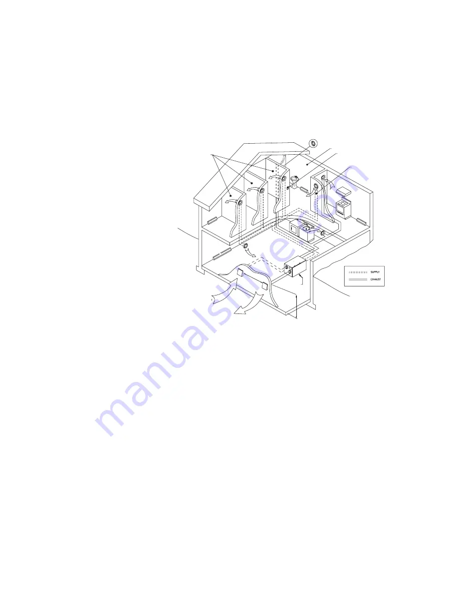
Fantech SER 1504N Скачать руководство пользователя страница 22

22

Bedrooms

Fresh Air

Exhaust Air

Central Control - optional

Fresh air to living room

Exhaust

Bathroom

18 inches
(460 mm)

6 feet 

(1800 mm)

ERV

INSTALLATION EXAMPLES

Example diagram only-duct configuration may change depending on model

It is the responsibility of the installer to ensure all ductwork is sized and installed as designed to ensure the system will perform as
intended.  All air movement devices have a performance curve.  The amount of air (CFM) that an ERV will deliver is directly related
to the total external static pressure (E.S.P.) of the system.  Static pressure is a measure of resistance imposed on the blower by
length of duct work/number of fittings used in duct work, duct heater etc.

Fully Dedicated System
(new construction)

Stale air drawn from key areas
of home (bathroom, kitchen,
laundry)

Fresh air supplied to main liv-
ing areas

ERV must be balanced

Содержание SER 1504N

Страница 1: ...f mechanical equipment i e a forced air furnace or air handler operating at a higher static After installation the compatibility of the two pieces of equipment must be confirmed by measuring the airfl...

Страница 2: ...g an authorized service centre near the purchaser or in the general area Fantech reserves the right to supply refurbished parts as replacements Transportation removal and installation fees are the res...

Страница 3: ...py energy recovery core configured for an efficient cross flow ventilation Core is 9 x 9 229 x 229 mm with a 15 380 mm depth Cores are manufactured to withstand extreme temperature variations FILTERS...

Страница 4: ...VENESS NET MOISTURE TRANSFER Submitted by Date Qty Model Comments Project Location Architect Engineer Contractor 0 0 2 0 4 0 6 0 8 1 1 2 1 4 1 6 0 25 50 75 100 125 150 175 200 cfm l s n x 0 47 in w g...

Страница 5: ...nufactured to withstand extreme temperature variations FILTERS Two 2 Washable Electrostatic Panel Type Air Filters they are 8 5 216mm x 15 380mm x 0 125 3mm PORT SELECTION Reversing Unit Units are shi...

Страница 6: ...MOISTURE TRANSFER Submitted by Date Qty Model Comments Project Location Architect Engineer Contractor 0 0 2 0 4 0 6 0 8 1 1 2 1 4 1 6 0 25 50 75 100 125 150 175 200 cfm l s n x 0 47 in w g Pa n x 248...

Страница 7: ...energy recovery core configured for an efficient cross flow ventilation Core is 12 x 12 305 x 305 mm with a 15 380 mm depth Cores are manufactured to withstand extreme temperature variations FILTERS...

Страница 8: ...CIENCY APPARENT SENSIBLE EFFECTIVENESS NET MOISTURE TRANSFER Submitted by Date Qty Model Comments Project Location Architect Engineer Contractor 0 0 2 0 4 0 6 0 8 1 1 2 1 4 1 6 0 25 50 75 100 125 150...

Страница 9: ...anufactured to withstand extreme temperature variations FILTERS Two 2 Washable Electrostatic Panel Type Air Filters they are 11 75 298mm x 15 380mm x 0 125 3mm PORT SELECTION Reversing Unit Units are...

Страница 10: ...CY APPARENT SENSIBLE EFFECTIVENESS NET MOISTURE TRANSFER Submitted by Date Qty Model Comments Project Location Architect Engineer Contractor 0 0 2 0 4 0 6 0 8 1 1 2 1 4 1 6 0 25 50 75 100 125 150 175...

Страница 11: ...cross flow ventilation Cores are 12 x 12 305 x 305 mm with a 11 34 288 mm depth Cores are manufactured to withstand extreme temperature variations and material is Flame proof paper and polyester based...

Страница 12: ...oject Location Architect Engineer Contractor 0 0 2 0 4 0 6 0 8 1 1 2 1 4 0 50 100 150 200 250 300 350 Net Supply Net Exhaust cfm l s n x 0 47 in w g Pa n x 248 Specifications and Ratings Model SER 320...

Страница 13: ...ith a 11 34 288 mm depth Cores are manufactured to withstand extreme temperature variations and material is Flame proof paper and polyester based synthetic paper FILTERS Four 4 Washable Electrostatic...

Страница 14: ...ents Project Location Architect Engineer Contractor 0 0 2 0 4 0 6 0 8 1 1 2 1 4 0 50 100 150 200 250 300 350 Net Supply Net Exhaust cfm l s n x 0 47 in w g Pa n x 248 Specifications and Ratings Model...

Страница 15: ...d electronic wall control wire Electronic air temperature probe gives this board accurate readings in order to minimize unnecessary defrost operation and the on board jumpers provide the user with the...

Страница 16: ...he heating season is higher than outdoor levels High humidity is a major cause of structure damage and IAQ problems such as mold and mildew 2 wire installation 4 wire installation 3 wire installation...

Страница 17: ...Dehumidistat is ideal for use in energy efficient houses where indoor humidity during the heating season is higher than outdoor levels High humidity is a major cause of structure damage and IAQ probl...

Страница 18: ...d tighten 1 Place Fastening hooks on the strapping board or the floor joists 1 Install the drain nipple Installing Drain Line Units with defrost Through normal operation and during its defrost mode th...

Страница 19: ...outer liner which acts as a vapor barrier must be completely sealed to outer wall and the ERV using tape and or caulking A good bead of high quality caulk ing preferably acoustical sealant will seal...

Страница 20: ...e See local building codes and practical tips To maximize airflow in the ductwork system all ducts should be kept short and have as few bends or elbows as possible Forty five degree are preferred to 9...

Страница 21: ...the ducting and fasten the collar to the wall or ceiling with screws 3 The Fantech grill MGE metal or PGE plastic airflow can be adjusted by rotating the inside unit It is recommended that the Grills...

Страница 22: ...to ensure the system will perform as intended All air movement devices have a performance curve The amount of air CFM that an ERV will deliver is directly related to the total external static pressur...

Страница 23: ...only 6 2m minimum separation recommended 18 460mm above grade minimum 3 Due to the differences in pressure between the ERV and the equipment it is being connected to the ERV s airflow must be confirm...

Страница 24: ...aration recommended 18 460 mm above grade minimum 5 Due to the differences in pressure between the ERV and the equipment it is being connected to the ERV s airflow must be confirmed on site using the...

Страница 25: ...mum 4 Due to the differences in pressure between the ERV and the equipment it is being connected to the ERV s airflow must be confirmed on site using the balancing procedure found in the installation...

Страница 26: ...or other manometer capable of reading from 0 to 0 25 in 0 62 Pa of water preferably to 3 digits of resolution The tube coming out of the top of the pitot is connected to the high pressure side of the...

Страница 27: ...ouble free use of your system Run through the system and verify the different operating modes ENERGY RECOVERY CORE FILTERS The motor The motors are factory balanced and lubri cated for life They requi...

Страница 28: ...nce ERV Locate the Grills high on the walls or under the baseboards install ceil ing mounted diffuser or Grills so as not to directly spill the supply air on the occupant eg Over a sofa Turn down the...

Страница 29: ...ng THERMOSTAT TERMINALS FURNACE 24 VOLT TERMINAL BLOCK FOUR WIRE TWO WIRE heating only TWO WIRE COOLING SYSTEM HRV ELECTRONIC BOARD WIRE JOINT Caution Never connect a 120 volt AC circuit to the termin...

Страница 30: ...30 ELECTRICAL WIRING DIAGRAMS SER 1504 SER 1504N SER 2004 SER 2004N...

Страница 31: ...31 ELECTRICAL WIRING DIAGRAMS SER 3204D SER 3204N...

Страница 32: ...chnological leadership position Article 301096 Item 401455 Rev Date 020905 United States 1712 Northgate Blvd Sarasota FL 34234 Phone 800 747 1762 941 309 6000 Fax 800 487 9915 941 309 6099 www fantech...

Отзывы: