


Electrical Connection
DO NOT CONNECT POWER SUPPLY UNTIL FAN IS COMPLETELY INSTALLED. MAKE SURE
ELECTRICAL SERVICE TO THE FAN IS LOCKED IN "OFF" POSITION.
1. This unit has rotating parts and safety precautions should be exercised during installation, operation and maintenance.
2. CAUTION: "For General Ventilation Use Only. Do Not Use To Exhaust Hazardous Or Explosive Materials And Vapors."
3. WARNING: TO REDUCE THE RISK OF FIRE, ELECTRIC SHOCK, OR INJURY TO PERSONS - OBSERVE THE
FOLLOWING:
a. Use this unit only in the manner intended by the manufacturer. If you have questions, contact the factory.
b. Before servicing or cleaning, switch power off at service panel and lock service panel to prevent fan from being switched
on accidentally. When the service disconnecting means cannot be locked, securelyfasten a prominent warning device, such
as a tag, to the service panel.
c. Installation work and electrical wiring must be done by qualified person(s) in accordance with all applicable codes and
standards, including fire-rated construction.
d. Sufficient air is needed for proper combustion and exhausting of gases through the flue (chimney) of fuel burning equipment
to prevent back drafting. Follow the heating equipment manufacturer's guidelines and safety standards such as those published
by the National Fire Protection Association (NFPA), the American Society of Heating, Refrigeration, and Air Conditioning
Engineers (ASHRAE) and the local code authorities.
e. When cutting or drilling into wall or ceiling, do not damage electrical wires or other hidden utilities.
f. Ducted fans must always be vented to the outdoors.
g. Install fan at least five feet above the floor.
5. WARNING! Check voltage at the fan to see if it corresponds to the motor nameplate.
GUARDS MUST BE INSTALLED WHEN FAN IS WITHIN REACH OF PERSONNEL OR WITHIN SEVEN (7) FEET OF WORKING
LEVEL OR WHEN DEEMED ADVISABLE FOR SAFETY.
Wiring Procedure
Please Note: The fan motor, capacitor and pressure switch
connections are pre-wired from the factory.
Step 1.
Remove the screws securing the terminal box cover
plate located on the side of the fan. All fan motor connections
are prewired to an electrical terminal strip. A 3/8" romex
type cable restraint connector will be needed to secure the
wiring through the knockout provided on the side of the
terminal box.
Step 2.
Bring incoming electrical service through the romex
connector and the fan knockout. Be sure to place the
connector nut over the wiring coming into the terminal box.
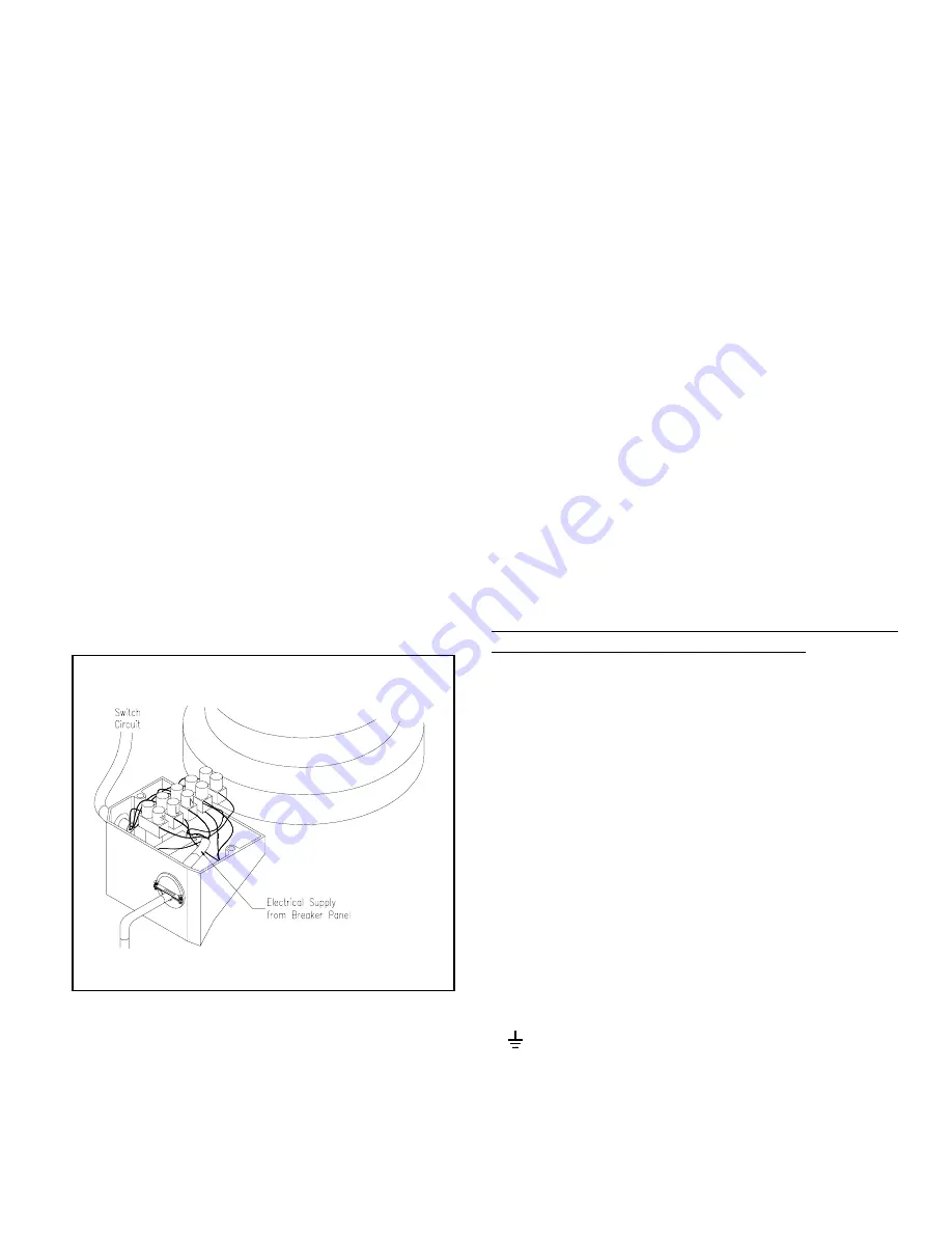
There are three open ports on the terminal strip. Using a
small regular screwdriver, tighten the Neutral (White) wire
of the incoming supply under the open terminal labelled "N".
Tighten the Line (Black) wire of the incoming supply under
the open terminal labelled "L". Tighten the Ground (Green)
wire of the incoming supply under the open terminal marked
" ". For reference, a wiring diagram is included on the
inside of the terminal box lid. For future reference, a
schematic is also shown on the back page of these
instructions.
Step 3.
Secure the romex connector. Secure the incoming
supply with the romex connector. Replace the fan terminal
box cover.
View of Terminal Strip