


12
13.
Remove the large retainer ring on top of the Torsion Body.
14.
Lift the torsion shaft assembly up and out of the Rheometer frame.
B.
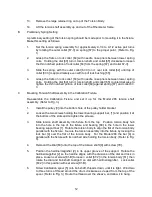
Preliminary Spring Setting
A preliminary setting of the torsion spring should be made prior to mounting it in the fixture.
Make this setting as follows:
1.
Set the torsion spring assembly for approximately 9-1/4 to 9-1/2 active pair turns
by rotating the outer collet [67-3] on spring [67] to the proper point. (Refer to Fig.
1)
2.
Grasp the flats on lock collet [64] with needle nose pliers between lower spring
coils. Holding the dial [60] turn it, torsion shaft, and collet [65] clockwise to loosen
the thin notched portion of lock collet [64] from the spring [67]. and collet 67-3].
3.
Slide the spring, with the outer collet [67-3] on it, over lock collet [64] until top of
collet [67-3] is approximately even with top of lock bushing [65].
4.
Grasp the flats on lock collet [64] with needle nose pliers between lower spring
coils. Holding the dial [60] turn it, torsion shaft, and collet [65] counterclockwise to
tighten the thin notched portion of lock collet [64] against spring [67]. and collet 67-
3
C.
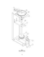
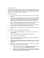
Mounting Torsion Shaft Assembly in the Calibration Fixture.
Re-assemble the Calibration Fixture and set it up for the Model 286 torsion shaft
assembly.
(Refer to Fig. 3).
1.
Install the pulley [3] into the bottom hole of the pulley holder bracket.
2.
Loosen the two screws holding the lower bearing support bar, [1] and position it at
the bottom of the slots and re-tighten the screws.
3.
Slide torsion shaft assembly into fixture from the top. Position torsion body hub
into the hole in the top of the fixture and bearing [68] in the hole in the lower
bearing support bar [1]. Rotate the torsion body to align the flat of the torsion body
parallel with the fixture. Secure the torsion assembly into the fixture by locking the
lock bar [4] over the flat of the torsion body. For the Model 286 the bar [4] is
parallel with the fixture with its notched side holding the torsion body. (Refer to Fig.
3).
4.
Remount the Dial [60] onto the top of the torsion shaft [9] with screw [79].
5.
Position the hairline/magnifier [2] in its upper groove of the support. Rotate the
hairline/magnifier [2] so the hairline aligns with the divisions of the dial and lock in
place. Loosen set screw [81-B] to loosen collet [67-2] in the torsion body [61], then
rotate the dial and bob shaft to align 0 on dial with hairline/magnifier. Lock collet
[67-2] in this position with set screw [81-B].
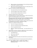
6.
Screw Calibration spool [5] onto bob shaft, threads down, until it is tight. Wind two
to three turns of thread around the drum clockwise as viewed from the top of the
spool. (Refer to Fig. 3.) Route the thread over the sheave, and allow it to hang.
Содержание 280
Страница 5: ...2 ...
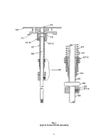
Страница 8: ...5 Fig 1 Typical Torsion Shaft Assembly ...
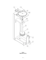
Страница 9: ...6 Fig 2 Model 280 Set Up ...
Страница 13: ...10 Fig 3 Model 286 Set Up ...


