Fanimation Involution FP4520 Series Скачать руководство пользователя страница 3

This Manual is Designed to Make it as Easy as Possible for You

to Assemble, Install, Operate, and Maintain Your Ceiling Fan

Unpacking Instructions

For your convenience, check-off each step.  As each step is completed, place a check mark.  This will ensure that all 
steps have been completed and will be helpful in 

fi

 nding your place should you be interrupted. 

Wiring outlet box and box connectors must be of type 

required by local code.  The minimum wire would be a 3-

conductor (2-wire with ground) of the following size:

NOTE:

  Place the parts from the loose parts bags in a small 

container to keep them from being lost.  If any parts are missing, 

contact your local retailer.

Tools Needed for Assembly

Materials

Wire Size A.W.G.

Installed Wire Length

14

12

Up to 50 ft.

50 - 100 ft.

NOTE:

  If you are uncertain of part description, refer to

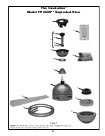
exploded view illustration. (Figure 1, page 13)

3

1. 

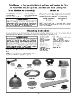
Check to see that you have received the following 

parts: 

• Fan Motor Assembly
• Switch Cup Adapter
  Assembly
• Adapter Cup Assembly
• Downrod/Hanger Ball
  Assembly
• Hanger Bracket
• Ceiling Canopy
• Canopy Screw Cover
• Motor Coupling Cover
• Floating Rings
• Lower Cover Assembly
• Wood Blades (2)
• CW40 Wall Control

Adapter Cup Assembly

Hardware Bags

CW40 Wall Control

Fan Motor Assembly

Lower Cover Assembly

Downrod/

Hanger Ball

Assembly

Hanger Bracket

• One Phillips head screwdriver
• One stepladder
• One ¼

˝

 blade screwdriver

• One wire stripper


Three wire connectors

  (supplied)

Ceiling Canopy

Blade Set

• Hardware bags:
   – ¼-20 x 15 mm (Counterweight & floating 
      rings to fan motor hub) 
      screws with lockwashers
   – 

3

/

16

-24 x


15 mm (blade to motor hub)

      washer-head screws & fiber washers
   – Phillips screwdriver, 4

˝

   – Four wire connectors
   – Counterweight
   – Nameplate Plug
   – Blade Balance Kit

Motor Coupling Cover

Floating Rings

WARNING

Do not install or use fan if any part is damaged or 

missing.  This product is designed to use only those 

parts supplied with this product and/or any accessories 

designated specifically for use with this product by 

Fanimation.  Substitution of parts or accessories not 

designated for use with this product by Fanimation could 

result in personal injury or property damage.  Contact 

your retail store for missing or damaged parts.

WARNING

Before assembling your ceiling fan, refer to section on 

proper method of wiring your fan (page 4).  If you feel you 

do not have enough wiring knowledge or experience, 

have your fan installed by a licensed electrician.

Switch Cup Adapter 

Assembly

Canopy

Screw Cover

Содержание Involution FP4520 Series

Страница 1: ...OWNER S MANUAL READ AND SAVE THESE INSTRUCTIONS Model No FP4520 The Involution Ceiling Fan Net Weight 9 07 kg 20 lbs...

Страница 2: ...tain amount of wobble is normal and should not be considered a problem or a defect LIMITED LIFETIME WARRANTY Extends to the original purchaser of a Fanimation Fan Important Safety Instructions WARNING...

Страница 3: ...ver Assembly Wood Blades 2 CW40 Wall Control Adapter Cup Assembly Hardware Bags CW40 Wall Control Fan Motor Assembly Lower Cover Assembly Downrod Hanger Ball Assembly Hanger Bracket One Phillips head...

Страница 4: ...n doubt Electrical and Structural Requirements Energy Efficient Use of Ceiling Fans Ceiling fan performance and energy savings rely heavily on the proper installation and use of the ceiling fan Here a...

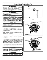
Страница 5: ...Cover on fan shown with open side facing up Figure 3 5 Reinstall the Hanger Ball Figure 1 on the Downrod as follows Route the three 80 wires and cable through the Hanger Ball Position the Pin through...

Страница 6: ...Figure 2 Outlet Box Hanger Bracket Outlet Box Hanger Bracket Screw 2 Supplied with Outlet Box Tab Downrod Hanger Ball Assembly WARNING Failure to seat tab in groove could cause damage to electrical w...

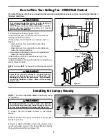
Страница 7: ...pleted WARNING To avoid possible fire or shock make sure that the electrical wires are completely inside the canopy housing and not pinched between the housing and the ceiling 1 Loosen the two shoulde...

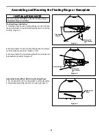
Страница 8: ...ashers provided Figures 1 2 3 Securely fasten the Counterweight with two screws and lock washers provided Figures 2 Assembly Option When Not Using Floating Rings 1 Do not assemble the Counterweight to...

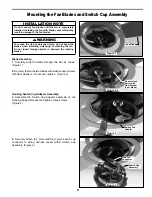
Страница 9: ...he color matching 9 pin switch cup connector to wiring harness socket within Switch Cup assembly Figure 4 Figure 3 Fan Blade Switch Cup Adapter Switch Cup Assembly Main Fan Connector Figure 2 Washer H...

Страница 10: ...cated on the Switch Cup Assembly Figure 5 6 Assemble the Lower Cover onto the assembled Switch Cup Adapter by twisting in the clockwise direction Don t over tighten Figure 6 7 Restore Power and your f...

Страница 11: ...box by turning the electricity on at the main fuse box 2 Your fan model is equipped with a 4 position 3 speed slide switch wall control The operating sequence is as follows 4th Position low speed 3rd...

Страница 12: ...bly P452005 10 Switch Cup Assembly with Wiring Harness AP452006BL 11 Lower Cover Assembly AP452070 12 Wall Control CW40 13 Hardware Bag Containing HDWFP4520 Blade Balance Kit BALKT HDWHW4520 Counterwe...

Страница 13: ...olution Model FP4520 Exploded View 1 3 4 2a 2b 2c 2d 2 NOTE The illustration shown is not to scale or its actual configuration may vary Product parts are subject to change without notice Figure 1 7 11...

Страница 14: ...other or against the interior wall of the switch housing CAUTION Make sure main power is turned off 5 Some fan motors are sensitive to signals from solid state variable speed controls Solid state con...

Страница 15: ......

Страница 16: ...Copyright 2008 Fanimation 2008 01 10983 Bennett Parkway Zionsville IN 46077 888 567 2055 FAX 866 482 5215 Outside U S call 317 733 4113 Visit Our Website www fanimation com...

Отзывы: