background image

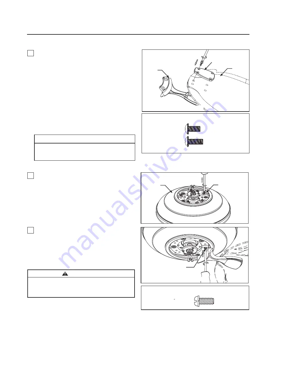
Blade Holder Cover

Blade

Motor Stops

Motor
Assembly

Blade 
Holder

14

x  10

1/4 -20

SCREWS

HARDWARE USED:

NOTE:  Periodically check Blade Holder hardware and re-
secure if necessary. (see Maintenance below)

WARNING

To reduce the risk of personal injury, do not bend the 
blade holders when installing, balancing the blades or 
cleaning the fan. Do not insert foreign objects in between 
the rotating blades.

3. 

Attach assembled blade holders to the motor  

2. 

 Remove and discard the motor stops from the

motor assembly by removing the screws. (Figure 2)

hub using the provided screws with lock washers. 
Make sure the screws securing the blade holders  
to the motor hub are tight and that the blade 
holders are properly seated. (Figure 3)

Figure 3

Screw
(2 per blade 
holder)

Figure 2

Figure 1

Assembling and Mounting the Fan Blades

Assembling and Mounting the Fan Blades 

x  20

#8-32

Serrated Head

Screw-Short

HARDWARE USED:

x  20

#8-32

Serrated Head

Screw-Long

Do not connect fan blades until the fan is completely

installed. Installing the fan with blades assembled

may result in damage to the fan blades.

CAUTION

NOTE: You will find the fan blade set packed in its own
carton and the blade holders and hardware bag in the
fan box.

NOTE: Assemble the B2 and B6 blades with short screws.
Assemble the B1, B3, B4, B5, B7 and B8 blades with long
screws.

1.

 Lay flat side of blade holder on a flat surface with 

the inside of the blade holder facing up.  This is the 
side with the threaded posts and pitched foot. 
Position the blade over the blade holder with the 
threaded posts showing. Make sure the bottom edge 
of the blade is fully seated against the blade holder. 
Place blade holder cover on top of the blade, 
positioning the holes over the threaded posts. With a 
Philips screwdriver, thread both screws into the posts 
but do not fully tighten. Prior to final tightening, 
position the centerline of the blade holder with the 
center of the end of the blade. Tighten both screws to 
secure the blade. (Figure 1)

Содержание distinction A1 series

Страница 1: ...s A1 C1 D1 OWNER S MANUAL READ AND SAVE THESE INSTRUCTIONS Distinction myFanimation Collection Fan Model Net Weight lbs Net Weight kgs 23 53 10 67 26 63 17 57 12 08 7 97 A1 Motor C1 Motor D1 Motor Onl...

Страница 2: ...f the fan and blades when cleaning painting or working near the fan Always turn off the power to the ceiling fan before servicing 4 Do not insert anything into the fan blades while the fan is operatin...

Страница 3: ...Wire Your Ceiling Fan A1 C1 11 10 How to Wire Your Ceiling Fan D1 12 13 Assembling and Mounting the Fan Blades 14 Installing the Switch Cup Cover 15 How to Operate Your Ceiling Fan A1 C1 16 17 How to...

Страница 4: ...ration 4 1 Check to see that you have received the following parts blade screwdriver Four wire connectors supplied WARNING Do not install or use fan if any part is damaged or missing This product is d...

Страница 5: ...draft which forces warm air near the ceiling down into the occupied space Remember to adjust your thermostat when using your ceiling fan additional energy and dollar savings could be realized with thi...

Страница 6: ...wo joists and takes the place of wooden blocking To avoid fire or shock follow all wiring instructions carefully Any electrical work not described in these instructions should be done or approved by a...

Страница 7: ...ll Set Screw Downrod 3B For D1 The fan comes with black white and green wires Separate and untwist the three wires and route them through the downrod Align the clevis pin holes in the downrod with the...

Страница 8: ...downrod Strip 1 2 inch from the end of each lead insulation off wire Figure 6 7 Completely remove one of each right hand screw on either side of the flap of the hanger bracket and retain the screws f...

Страница 9: ...the screw cover from the ceiling canopy Figure 2 3 Route your fan wires through the ceiling canopy Align the three big slots in the canopy to the three screws in the motor coupler Firmly attach the ca...

Страница 10: ...rews pass through slotted holes of the hanger bracket Figure 3 2 Pull the electric wires in the outlet box down through the opening in the hanger bracket If necessary strip wire ends Bend wires up and...

Страница 11: ...efully push leads into the outlet box with the white and green leads to one side of the box and the black leads towards the other side The wires should be spread apart with the grounded conductor and...

Страница 12: ...nd Green Wire from Fan Ground Green Wire from Hanger Ball Ground Listed Outlet Box Household Supply Black Wire from Supply Black Wire from Fan Green Wire from Supply Ground White Wire from Supply Whit...

Страница 13: ...ween the screws Figure 4 Figure 1 NOTE MOTOR WIRES HAVE BEEN OMITTED FROM DIAGRAM Figure 2 Hanger Bracket Screw L Slot Ceiling Canopy Slide the ceiling canopy over the mounting bracket with the two lo...

Страница 14: ...HARDWARE USED x 20 8 32 Serrated Head Screw Long Do not connect fan blades until the fan is completely installed Installing the fan with blades assembled may result in damage to the fan blades CAUTIO...

Страница 15: ...re 1 3 Assemble the inner switch housing assembly to the adapter switch housing assembly using the key slots Replace the screw and securely tighten all two screws Figure 3 2 Remove one of the two scre...

Страница 16: ...witch Doing so could result in damage to the ceiling fan s remote control unit 16 How to Operate Your Ceiling Fan A1 C1 MAIN FUSE BOX Figure 2 Figure 1 For illustrative purposes only not intended to c...

Страница 17: ...at you must press the fan off button within 30 senconds after restoring power Re pairing your device is not necessary after replacing the battery Each fanSync receiver can pair to five different trans...

Страница 18: ...ge dimmer switch not included to control fan speed will damage the fan To reduce the risk of fire or electrical shock do not use a full range dimmer switch to control the fan speed Figure 1 SET Dip Sw...

Страница 19: ...force warm air downward without a noticeable breeze Figure 5 5 Remote functiolns Figure 5 Indicator LED light fan speed and light dimer indicator Fan Speed button Turn off the fan Light button Turn O...

Страница 20: ...et PA107 PA107 PA107 Part D1 Hanger Bracket Assembly Hanger Ball Downrod Assembly 3 Sloped Hanger Ball Canopy Trim Ring Assembly 8 Hand Held Remote Hardware Bag Containing Blade Holder Mounting Hardwa...

Страница 21: ...PF3 1 Hardware Bag HDWF1F3 2 F3 Optional Glass G4 G5 G6 Before discarding packaging materials be certain all parts have been removed NOTE The illustration shown is not to scale and actual FRQ JXUDWLRQ...

Страница 22: ...VKRZQ LV QRW WR VFDOH RU LWV DFWXDO FRQ JXUDWion may vary Optional Fan Blade How To Order Parts When ordering repair parts always give the following information Part Number Part Description Fan Model...

Страница 23: ...i t a r u g i f n o c s t r a p l a u t c a s t i r o e l a c s o t t o n s i n w o h s n o i t a r t s u l l i e h T y Exploded View Illustration 23 A1 C1 15 1 2 4 3 5 6 7 7a 7b 8 9 10 11 12 purchas...

Страница 24: ...o i t a r u g i f n o c s t r a p l a u t c a s t i r o e l a c s o t t o n s i n w o h s n o i t a r t s u l l i e h T y Exploded View Illustration 24 D1 14 13 15 1 2 4 3 5 6 7 7a 7b 8 9 10 11 12 pu...

Страница 25: ...ot securely fastened 6 Fan blades out of balance 1 Tighten both setscrews and nuts securely in downrod support 2 Tighten the setscrew in the downrod hanger ball assembly 3 Check to be sure screws whic...

Страница 26: ...Copyright 2015 Fanimation 2015 10 V 01 10983 Bennett Parkway Zionsville IN 46077 888 567 2055 FAX 866 482 5215 Outside U S call 317 733 4113 Visit Our Website www fanimation com...

Страница 27: ...PIETARIO LEA Y GUARDE ESTAS INSTRUCCIONES Modelo N A1 C1 D1 Distinction Colecci n myFanimation Modelo Peso neto lbs Peso neto kgs 23 53 10 67 26 63 17 57 12 08 7 97 A1 Motor C1 Motor D1 Motor Solo par...

Страница 28: ...ropietario para ver los requisitos de soporte Si tiene dudas consulte a un electricista calificado Las aspas del ventilador deben instalarse por lo menos a 2 m 7 pies del suelo a fin de evitar un cont...

Страница 29: ...o en conjunci n con ste excepto en los casos en los que la ley as lo disponga Esta garant a le otorga derechos legales especiales y es posible que tambi n goce de otros derechos que pueden variar seg...

Страница 30: ...eceptor A1 C1 Bolsas de accesorios Tornillos con arandelas de seguridad de 1 4 20 soporte de aspas a buje del motor 8 32 Tornillo corto de cabeza dentada 8 32 Tornillo largo de cabeza dentada aspa a s...

Страница 31: ...salgunassugerencias para asegurar un rendimiento eficiente del producto Selecci n del lugar de montaje adecuado Los ventiladores de techo se deben instalar en el centro de la habitaci n a 2 13 m 7 pie...

Страница 32: ...tar posibles descargas el ctricas aseg rese de que la electricidad est desconectada en la caja de fusibles principal antes de realizar la instalaci n el ctrica Toda instalaci n el ctrica debe cumplir...

Страница 33: ...Paso 5 Figura 1 Pasador de horquilla Pasador de horquilla Pasador de horquilla Soporte del barral Soporte del barral Soporte del barral Pasador Tornillo de fijaci n Bola para colgar Clip de horquilla...

Страница 34: ...aci n Pase los cables de 2 03 m 80 para techo a trav s de la semiesfera de la semiesfera Pase el pasador a trav s de los dos orificios en el barral y alinee la semiesfera de modo que el pasador quede...

Страница 35: ...etire el la cubierta del tornillo de la base desde el capuch n de techo Figura 2 3 Introduzca los cables de su ventilador a trav s de la cubierta del techo Alinee las tres ranuras de la cubierta con l...

Страница 36: ...iento a un electricista autorizado ya que la conexi n a tierra es fundamental para un funcionamiento seguro 1 Fije bien el soporte de suspensi n a la caja de distribuci n con los tornillos y las arand...

Страница 37: ...tiene conexi n a tierra pida consejo a un electricista certificado ya que debe tener conexi n a tierra para un funcionamiento seguro Para evitar una posible descarga el ctrica aseg rese de cortar la...

Страница 38: ...o neutro mediante el conector provisto de forma segura Conecte el conductor negro del motor del ventilador y el conector azul al conducto negro mediante el conector provisto de forma segura Figura 2 A...

Страница 39: ...rnillos Figura 1 Levante el ventilador del enganche del soporte colgante e instale su ventilador deslizando la cubierta del techo con dos tornillos aflojados en las ranuras en forma de L de la cubiert...

Страница 40: ...obre el aspa y alinee los orificios sobre los pilotes roscados Con un destornillador Phillips enrosque ambos tornillos en los pilotes pero no los ajuste por completo Antes de ajustarlos por completo a...

Страница 41: ...nte Figura 1 3 Instale la cubierta interior en la cubierta del adaptador usando las ranuras claves Vuelva a colocar el otro tornillo y fije los dos tornillos adecuadamente Figura 3 2 Extraiga uno de l...

Страница 42: ...el riesgo de incendio o descarga el ctrica no utilice dicho regulador para controlar la velocidad del ventilador Figura 1 Figura 2 Figura 3 Figura 1 Solo para referencia visual no ha sido dise ado par...

Страница 43: ...n y mantenga pulsado el bot n de apagado del ventilador durante 1 3 segundos El ventilador se apagar Vu lvalo a encender a velocidad media para indicar que el proceso de emparejamiento se ha completa...

Страница 44: ...se caracteriza por la funci n de aprendizaje autom tico No hay interruptores de frecuencia en la unidad del receptor El receptor ya que se escanear autom ticamente la frecuencia desde el mando a dist...

Страница 45: ...j El flujo del aire fuerza el aire caliente hacia abajo sin una brisa visible Figura 5 5 Funciones del control remoto Figura 5 Luz LED del indicador Velocidad del ventilador e indicador atenuante de l...

Страница 46: ...110BL APA111 TR205 RC205QBT D1 APA114 APA105 APA110BL Cubierta interior Unidad del receptor Conectores de cables 4 Kit de balanceo de aspas KTBAL 8 32 Tornillo corto de cabeza dentada 21 8 32 Tornillo...

Страница 47: ...ezas NOTA la ilustraci n que se muestra no est hecha a es FDOD VX FRQ JXUDFLyQ UHDO SXHGH YDULDU G2 G3 G1 G1 Unidad del kit de iluminaci n Bombilla 4 Herramienta de fijaci n del cristal Z0857 3 1 1 2...

Страница 48: ...B760 B854 B860 3LH D 1 Antes de desechar los materiales de embalaje aseg rese de haber extra do todas las piezas NOTA la ilustraci n que se muestra no est hecha a es FDOD VX FRQ JXUDFLyQ UHDO SXHGH Y...

Страница 49: ...NOTA OD LOXVWUDFLyQ TXH VH PXHVWUD QR HVWi KHFKD D HV FDOD VX FRQ JXUDFLyQ UHDO SXHGH YDULDU 49 A1 C1 15 1 2 4 3 5 6 7 7a 7b 8 9 10 11 12 14 13 Ilustraci n del despiece Se compra por separado...

Страница 50: ...50 D1 14 13 15 1 2 4 3 5 6 7 7a 7b 8 9 10 11 12 NOTA OD LOXVWUDFLyQ TXH VH PXHVWUD QR HVWi KHFKD D HV FDOD VX FRQ JXUDFLyQ UHDO SXHGH YDULDU Ilustraci n del despiece Se compra por separado...

Страница 51: ...n flojos 4 Los soportes de aspas no est n colocados correctamente 5 El soporte de suspensi n o la caja de distribuci n el ctrica del techo no est n bien asegurados 6 Las aspas del ventilador est n de...

Страница 52: ...Copyright 2015 Fanimation 2015 10 V 01 10983 Bennett Parkway Zionsville IN 46077 888 567 2055 FAX 866 482 5215 Outside U S call 317 733 4113 Visit Our Website www fanimation com...

Отзывы: