BLITZ
™
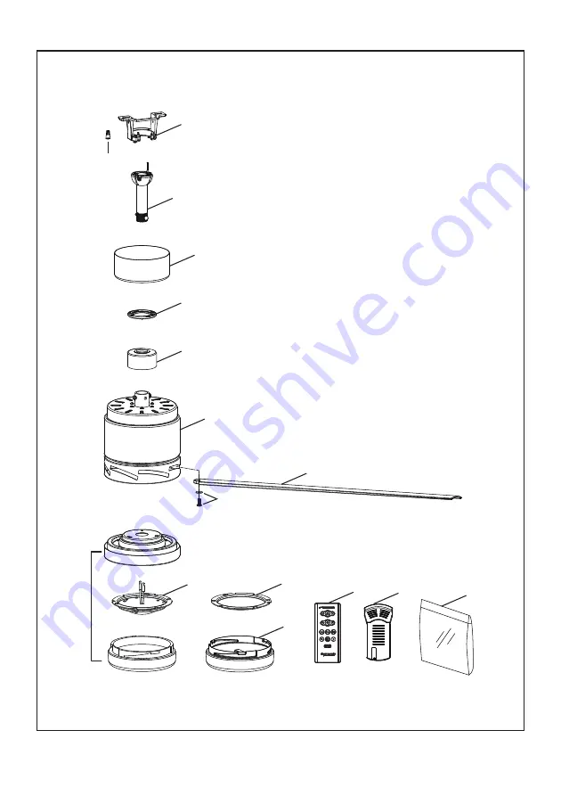
Model LP8377LBNExploded-View Illustration
1
2
3
4
5
6
7
9
10
12
14
13
11
8
NOTE:
The illustration shown is not to scale or its actual configuration may vary.
Product/parts are subject to change without notice.
19
Страница 1: ...se Date ATTACH YOUR RECEIPT HERE AND REGISTER YOUR FAN AT FANIMATION COM READ AND SAVE THESE INSTRUCTIONS For best and quick service please provide date code You can find the date code on the Carton Handheld Remote inside of the battery compartment Receiver or top of Fan Housing Net Weight 16 12 lbs 7 31 kgs BLITZ CEILING FAN MODEL LP8377LBN ITEM 2483971 Español p 21 ...
Страница 2: ...te control unit operate the equipment CAUTION Changes or modifications not expressly approved by the party responsible for compliance could void the user s authority to WARNING This product is designed to use only those parts supplied with this product and or accessories designated specifically for use with this product Using parts and or accessories not designated for use with this product could ...
Страница 3: ...ce center 4 If any other part of your light kit fails at any time within five years after original purchase due to a defect in materials or workmanship we will repair or replace at our option the defective part free of charge for parts and labor performed at our national service center 5 Because of varying climate conditions this warranty does not cover changes in the finish including rusting pitt...
Страница 4: ...sembly Not Included One Phillips head screwdriver One blade screwdriver One stepladder One wire stripper 1 Check to see that you have received the following parts NOTE If you are uncertain of part description refer to exploded view illustration WARNING Do not install or use fan if any part is damaged or missing This product is designed to use only those parts supplied with this product and or any ...
Страница 5: ...our Fanimation Retailer for optional mounting accessories Turn Off When Not in the Room Ceiling fans cool people not rooms If the room is unoccupied turn off the ceiling fan to save energy Your new ceiling fan will require a grounded electrical supply line of 120 volts AC 60 HZ 15 Amp Circuit Electrical code requires use of a fan rated outlet box to support the extra weight and motion associated w...
Страница 6: ... of wooden blocking To avoid fire or shock follow all wiring instructions carefully Any electrical work not described in these instructions should be done or approved by a licensed electrician Figure 3 CEILING JOIST CEILING OUTLET BOX To reduce the risk of fire electric shock or personal injury mount to outlet box marked acceptable for fan support of 15 9 kg 35 lbs or less and use mounting screws ...
Страница 7: ...rom the bottom of the downrod Retain the pin and clip for reinstallation in Step 5 Figure 2 Figure 2 WARNING It is critical that the clevis pin in the downrod support is properly installed and the set screws and nuts are securely tightened Failure to do so could result in the fan falling 5 Thread downrod into the downrod support on top of the motor Install the clevis pin by aligning the holes in t...
Страница 8: ...t screw in the hanger ball A loose set screw could create fan wobble Figure 7 8 Cut off excess lead wire approximately 6 to 9 inches above top of the downrod Strip insulation off 1 2 inch from the end of each lead wire Figure 8 NOTE All set screws must be checked and retightened where necessary before installation How to Assemble Your Ceiling Fan Continued Figure 9 9 Remove one of the two shoulder...
Страница 9: ...options are not available For angled ceilings note the angle can be no more than 19 WARNING To avoid possible fire or shock be sure electricity is turned off at the main fuse box before hanging Figure 1 WARNING The fan must be hung with at least 7 of clearance from floor to ceiling fan Figure 2 WARNING Failure to seat tab in groove could cause damage to electrical wires and possible shock or fire ...
Страница 10: ...ol Figure 1 NOTE The remote unit has 32 different code other remote units simply change the combination code NOTE Factory setting is all up Do not use this position 2 Slide the receiver into the hanger bracket before wiring as shown in figure 3 Receiver Unit MAIN FUSE BOX Figure 2 NOTE If you are not sure if the outlet box is grounded contact a licensed electrician for advice as it must be grounde...
Страница 11: ...x RED BLACK WHITE BLK ANT GRAY YELLOW GREEN Ground Wire From Hanger Bracket GREEN Ground wire From Ceiling GREEN Ground Wire From Hanger Ball GREEN YELLOW Ground wire 2 From Receiver BLACK WHITE BLUE 4 After connections have been made and put the white and green leads to one side and the black leads towards the other side the connection should be turned upward and carefully push leads into the out...
Страница 12: ...de the canopy housing and not pinched between the housing and the ceiling Canopy Screw Cover Ceiling Canopy Figure 1 Figure 2 12 Figure 1 How to Assemble Your Ceiling Fan Blades x 21 x 21 Flat Washers 3 16 24 Serrated Head Screws HARDWARE USED 3 16 24 Serrated Head Screw with Flat Washer 3 per blade INSTALLATION NOTE Do not connect fan blades until the fan is completely installed Installing the fa...
Страница 13: ...in the light kit Retain the screw for later and slightly loosen the remaining two screws Figure 3 4 If installing the light kit skip this step Assemble the light kit wire cover to the light kit using the two key slots Replace the removed screw and secure all three screws Figure 4 5A For use with light kit Connect the 2 single pin connectors from the LED assembly to the 2 single pin connectors from...
Страница 14: ...ed to control fan speed will damage the fan To reduce the risk of fire or electrical shock do not use a full range dimmer switch to control the fan speed Figure 1 2 Restore electrical power to the outlet box by turning the electricity on at the main fuse box Figure 2 3 Remove the battery cover from remote control by screwdriver and retain the screw for later Figure 3 Figure 1 Figure 2 For illustra...
Страница 15: ... on the remote control with previously removed screw by screwdriver Figure 6 7 Remote functions Figure 7 Indicator LED light fan speed and light dimmer indicator button Tap once to turn off the fan Press and hold this button for 5 seconds to turn on or turn off the buzzer Fan Speed Turn on fan and turn speed up Turn on fan and turn speed down Light button Turn ON OFF the light Increase light outpu...
Страница 16: ...Figure 1 Attach wall plate using the two provided screws Periodic cleaning of your new ceiling fan is the only maintenance necessary When cleaning use only a soft brush or lint free cloth to avoid scratching the finish Abrasive cleaning agents are not required and should be avoided to prevent damage to finish Periodic light dusting of the blades is recommended A feather duster will work best Avoid...
Страница 17: ...ol 4 Make sure reverse switch position is all the way to one side 4 Reverse switch in neutral position 1 Blades not attached to fan 1 Tighten both setscrews and nuts securely in downrod support 1 Setscrew and nut in downrod support is loose 2 Loose screws in motor housing 2 Tighten the setscrew in the downrod hanger ball assembly 2 Setscrew in downrod hanger ball assembly is loose 3 Check to make ...
Страница 18: ...umber located on downrod support Hardware Bag Containing 3 16 24 Serrated Head Screws 22 Stainless Flat Washers 22 Blade Mounting Hardware Bag Containing Motor Coupling Cover Assembly Motor Assembly Downrod Hanger Ball Assembly Ceiling Canopy Parts List Model LP8377LBN Before discarding packaging materials be certain all parts have been removed How To Order Parts When ordering repair parts always ...
Страница 19: ...l LP8377LBN Exploded View Illustration 1 2 3 4 5 6 7 9 10 12 14 13 11 14 8 14 NOTE The illustration shown is not to scale or its actual configuration may vary Product parts are subject to change without notice 19 ...
Страница 20: ...2020 03V 01 Copyright 2020 Fanimation 10983 Bennett Parkway Zionsville IN 46077 Phone 888 567 2055 Outside U S 317 733 4113 FAX 866 482 5215 FANIMATION COM ...
Страница 21: ...UÍ Y REGISTRE SU VENTILADOR EN FANIMATION COM LEA Y GUARDE ESTAS INSTRUCCIONES Para ofrecer un servicio rápido y de calidad por favor suministre el código de fecha Puede encontrar el código de fecha en el paquete en el mando a distancia dentro del compartimento de las pilas en el receptor o en la parte superior de la carcasa del ventilador Peso neto 7 31 kgs 16 12 lbs MODELO LP8377LBN ARTÍCULO 248...
Страница 22: ...e en tan solo 2 horas Asegure siempre por completo el compartimento de la pila Si el compartimento de la pila no está cerrado de forma segura deje de utilizar el mando a distancia del producto extraiga las pilas y manténgalo alejado del alcance de los niños Si piensa que las pilas pueden haber sido tragadas o colocadas dentro de cualquier parte del cuerpo humano busque asistencia médica inmediatam...
Страница 23: ...período de un año El cliente se hará responsable de todos los gastos de remoción o reinstalación y envío del producto para reparaciones o sustitución 3 Si otra pieza del ventilador fallara dentro del período de tres años a partir de la fecha de compra original debido a un defecto en los materiales o en la fabricación repararemos o sustituiremos según creamos conveniente la pieza defectuosa sin car...
Страница 24: ...pletar todos los pasos y podrá saber desde dónde retomar si fuera interrumpido 1 Verifique que haya recibido las siguientes piezas NOTA Si no está seguro de la descripción de una pieza consulte la ilustración del despiece 24 Bolsas de accesorios Unidad del soporte de suspensión 1 Capuchón de techo 1 Cubierta para el tornillo del capuchón 1 Cubierta de unión del motor 1 Juego de aspas 1 Ensamble de...
Страница 25: ... flujo de aire óptimo Consulte en su tienda minorista de Fanimation para obtener accesorios de montaje opcionales Apague el ventilador cuando no se encuentre en la habitación Los ventiladores son para refrescar a la gente no a las habitaciones Si la habitación está vacía apague el ventilador de techo para ahorrar energía Su nuevo ventilador de techo requiere una línea de suministro eléctrico con c...
Страница 26: ...rte de lámparas no son aptas para soporte de ventiladores y es posible que deban reemplazarse Consulte a un electricista calificado si tiene dudas ADVERTENCIA Apagar el interruptor de pared no es suficiente Para evitar posibles descargas eléctricas asegúrese de que la electricidad esté desconectada en la caja de fusibles principal antes de realizar la instalación eléctrica Toda instalación eléctri...
Страница 27: ...gar Retener el pasador y clip para la reinstalación en el paso 5 Figura 2 Figura 2 5 Enrosque el soporte de la varilla y alinee los orificios de la clavija de horquilla en ambas piezas Instale la clavija de horquilla y asegúrela con la pinza de horquilla Fije los dos tornillos de presión y las tuercas de seguridad en el soporte de la varilla interior Figura 5 Cómo ensamblar el ventilador de techo ...
Страница 28: ...a 2 2 8 6 c m 7 Vuelva a colocar la semiesfera en el barral como se indica a continuación Pase los cables de negro blanco azul rojo gris amarillo y cable de soporte para techo a través de la semiesfera Pase el pasador a través de los dos orificios en el barral y alinee la semiesfera de modo que el pasador quede atrapado en la ranura de la parte superior de la misma Empuje la semiesfera hacia arrib...
Страница 29: ...ga eléctrica asegúrese de cortar la alimentación eléctrica de la caja de fusibles principal antes de colgar el ventilador Figura 1 ADVERTENCIA La caja de salida debe estar bien asegurada La abrazadera para colgar debe estar bien asentada contra la caja de salida Si la caja de salida está empotrada retire el panel hasta que la abrazadera haga contacto con la caja Si la abrazadera y o la caja de sal...
Страница 30: ...ilador tiene 32 combinaciones diferentes de códigos Para evitar posibles interferencias desde o hacia otros mandos a distancia modifique el código de combinación de su transmisor y receptor Para evitar una posible descarga eléctrica asegúrese de cortar la alimentación eléctrica de la caja de fusibles principal antes de alambrado el ventilador Figura 2 ADVERTENCIA NOTA Si no está seguro de si la ca...
Страница 31: ... Conductor Negro Blanco Conductor Blanco Conductor Negro Conductor Azul Conductor Amarillo antena Verde Amarillo puesta a tierra 2 del Receptor Verdeo puesta a tierra del techo Verdeo puesta a tierra del soporte de suspensión Verdeo puesta a tierra del la bola para colgar Conductor Rojo Conductor Gris Conductor blanco del suministro Conductor verde de la bola para colgar puesta a tierra Caja de sa...
Страница 32: ...empujarse con cuidado en el cuadro de juntura y de que no estén aprisioel techo Tornillo de reborde Figura 1 Figura 2 Capuchón de techo Cubierta para el tornillo del capuchón 32 Cómo ensamblar las aspas del ventilador de techo Figura 1 x 21 x 21 Arandela plana 3 16 24 Tornillo de cabeza dentada Aditamentos utilizados Tornillos con cabeza de dentada de 3 16 24 con arandelas de 3 por aspa 1 Deslice ...
Страница 33: ...guarde los tornillos para pasos posteriores Afloje levemente los otros dos tronillos Figura 3 4 Si desea instalar el kit de iluminación sáltese este paso Instale la cubierta del cable del kit de iluminación en la ensamble de la placa de iluminación usando las dos ranuras con clave Sustituya el tornillo extraído y fije bien los tres tornillos Figura 4 5A Opción A Para su uso con el kit de iluminaci...
Страница 34: ... los tipos de controles Cómo utilizar su ventilador de techo Principal Caja De Fusibles 1 IMPORTANTE El uso de un regulador de la intensidad completa no incluido para controlar la velocidad del ventilador dañará el dispositivo Para reducir el riesgo de incendio o descarga eléctrica no utilice dicho regulador para controlar la velocidad del ventilador Figura 1 2 Restaure la fuente de alimentación d...
Страница 35: ...ando a distancia con un tornillo retirados previamente Figura 6 Mando a distancia Interruptores Figura 5 Figura 6 Cómo utilizar su ventilador de techo cont 7 Funciones del control remoto Figura 7 Luz LED del indicador Velocidad del ventilador e indicador atenuante de la iluminación Botón Toque este botón apaga el ventilador Mantenga pulsado el botón durante 5 segundos para encender o apagalo el zu...
Страница 36: ...isa refrigerante hacia abajo Invierno El ventilador funciona en el sentido de las agujas del reloj El flujo del aire fuerza el aire caliente hacia abajo sin una brisa visible 36 1 Instalación de la placa de la pared Figura 1 Fije la placa de la pared usando los dos tornillos suministrados Cómo instalar su mando a distancia Limpieza de las aspas Mantenimiento El único mantenimiento necesario para e...
Страница 37: ...terruptor están flojas 3 Pila agotada del mando a distancia 4 Asegúrese de que el conmutador inversor esté completamente a un lado 4 El conmutador inversor se encuentra en posición neutra 4 Algunos motores de ventilador son sensibles a las señales de los controles de velocidad de estado sólido variables Los controles de estado sólido no son recomendables Escoja un método de control alternativo 4 R...
Страница 38: ...ara el montaje de aspas que contiene Cubierta de unión del motor Unidad del motor Unidad del barral de la semiesfera Capuchón de techo Unidad del soporte de suspensión Lista de piezas Modelos N LP8377LBN N de Ref Descripción Pieza N Antes de desechar los materiales de embalaje asegúrese de haber extraído todas las piezas Cómo hacer un pedido de piezas Al hacer un pedido de piezas de repuesto propo...
Страница 39: ...BLITZ 1 2 3 4 5 6 7 9 10 12 14 13 11 14 8 14 Modelo LP8377LBN Ilustración del despiece NOTA La ilustración que se muestra no está hecha a escala y su c guración real y o terminación puede variar 39 ...
Страница 40: ...2020 03V 01 Copyright 2020 Fanimation 10983 Bennett Parkway Zionsville IN 46077 Llame Sin Cargo al 888 567 2055 Desde fuera de los EE UU llame al 317 733 4113 www fanimation com FAX 866 482 5215 ...