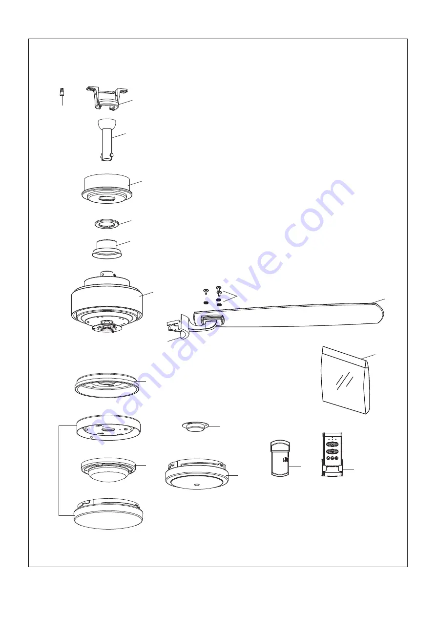
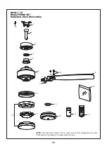
NOTE: The illustration shown is not to scale or its actual configuration may vary.
Product/parts are subject to change without notice.
Benito v2
Model FP8003B**
Exploded-View Illustration
™
20
16
1
2
3
4
5
6
7
9
10
8
12
11
15
14
13
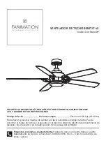
Страница 1: ...y Friday ATTACH YOUR RECEIPT HERE AND REGISTER YOUR FAN AT FANIMATION COM READ AND SAVE THESE INSTRUCTIONS MODEL FP8003B Espa ol p 22 Date Code Purchase Date For best and quickest service please provi...
Страница 2: ...a fan is identified for equipment grounding then it should be connected to an equipment grounding conductor WARNING TO REDUCE THE RISK OF ELECTRIC SHOCK THIS FAN MUST BE INSTALLED WITH A GENERAL USE...
Страница 3: ...es the right to modify or discontinue any product at any time and may substitute any part under this warranty 8 Under no circumstances may a fan be returned without prior authorization from Fanimation...
Страница 4: ...for use with this product by Fanimation Substitution of parts or accessories not designated for use with this product by Fanimation could result in personal injury or property damage Contact your ret...
Страница 5: ...r Fanimation Retailer for optional mounting accessories Turn Off When Not in the Room Ceiling fans cool people not rooms If the room is unoccupied turn off the ceiling fan to save energy Your new ceil...
Страница 6: ...of wooden blocking To avoid fire or shock follow all wiring instructions carefully Any electrical work not described in these instructions should be done or approved by a licensed electrician Figure 3...
Страница 7: ...ough the downrod Figure 3 4 Insert downrod into the downrod support on top of the motor Install the clevis pin by aligning the holes in the downrod support with holes in the downrod Secure clevis pin...
Страница 8: ...A loose set screw could create fan wobble Figure 6 7 Cut off excess lead wire approximately 6 to 9 inches above top of the downrod Strip insulation off 1 2 inch from the end of each lead wire Figure...
Страница 9: ...racket grounding wire and safety cable are pulled through the downrod between the hanger bracket and the outlet box so that electrical connections can be made later 4 Carefully lift the fan and seat t...
Страница 10: ...tact a licensed electrician for advice as it must be grounded for safe operation CAUTION INCORRECT WIRE CONNECTION WILL DAMAGE THIS RECEIVER 1 To set the code on receiver unit slide dip switches to th...
Страница 11: ...and that no bare wire is visible at the wire connectors except for the ground wire Do not operate fan until the blades are in place Noise and motor damage could result 4 After connections have been ma...
Страница 12: ...lly assemble and tighten second shoulder screw that was previously removed Figure 1 2 Securely attach and tighten the canopy screw cover over the shoulder screws in the hanger bracket utilizing the ke...
Страница 13: ...ects in between the rotating blades WARNING Blade Blade Holder 3 16 24 Serrated Head Screw and Flat Washer 3 each per blade 1 Position the blade over the blade holder with threaded posts showing Make...
Страница 14: ...ity for examination or repair 3 Remove the three screws in the light plate assembly and retain the screws for later Figure 3 Figure 3 Light Plate Assembly Figure 1 Motor Assembly 2 Assemble the light...
Страница 15: ...clockwise direction Figure 9 Light Wire Cap LED Kit Steel Cap LED Kit Figure 8 Figure 6 Figure 7 6 For use with light kit C Secure the glass to LED kit by twisting in a clockwise direction Twist the...
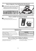
Страница 16: ...tery included in hand held remote transmitter with fan power off Then follow the remote code setting process If not used for long periods of time remove battery to prevent damage to transmitter Store...
Страница 17: ...an is the only maintenance necessary When cleaning use only a soft brush or lint free cloth to avoid scratching the finish Abrasive cleaning agents are not required and should be avoided to prevent da...
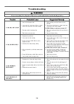
Страница 18: ...FAN WILL NOT START 2 FAN SOUNDS NOISY 3 FAN WOBBLES EXCESSIVELY 4 NOT ENOUGH AIR MOVEMENT 1 Fuse or circuit breaker blown 2 Loose power line connections to the fan or loose switch wire connections in...
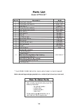
Страница 19: ...Hardware Bag Containing Motor Coupling Cover Assembly Motor Assembly Downrod Hanger Ball Assembly Ceiling Canopy Parts List Model FP8003B Before discarding packaging materials be certain all parts ha...
Страница 20: ...ration shown is not to scale or its actual configuration may vary Product parts are subject to change without notice Benito v2 Model FP8003B Exploded View Illustration 20 16 1 2 3 4 5 6 7 9 10 16 8 16...
Страница 21: ...2021 03 V 01 Copyright 2021 Fanimation 10983 Bennett Parkway Zionsville IN 46077 Phone 888 567 2055 Outside U S 317 733 4113 FAX 866 482 5215 FANIMATION COM...
Страница 22: ...EN FANIMATION COM LEA Y GUARDE ESTAS INSTRUCCIONES 6 MODELO FP8003B VENTILADOR DE TECHO BENITO v2 C digo de fecha Fecha de compra Para ofrecer un servicio r pido y de calidad por favor suministre el...
Страница 23: ...te producto est dise ado para ser usado s lo con las piezas suministradas o los accesorios indicados espec ficamente para el mismo Si utiliza piezas o accesorios que no est n indicados para su uso con...
Страница 24: ...esente Fanimation niega todas las garant as impl citas que incluyen entre otras la comerciabilidad y la aptitud para determinado fin hasta donde la ley lo permita Algunos estados no permiten limitacio...
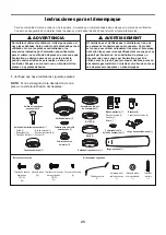
Страница 25: ...comodidad marque cada uno de los pasos A medida que completa cada paso coloque una marca de verificaci n Con esto se asegurar de completar todos los pasos y podr saber desde d nde retomar si fuera in...
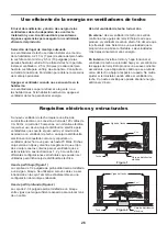
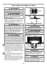
Страница 26: ...para un flujo de aire ptimo Consulte en su tienda minorista de Fanimation para obtener accesorios de montaje opcionales Apague el ventilador cuando no se encuentre en la habitaci n Los ventiladores so...
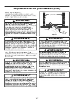
Страница 27: ...A fin de evitar incendios o descargas el ctricas siga con cuidado todas las instrucciones de instalaci n el ctrica Cualquier trabajo el ctrico que no se describa en estas instrucciones deber ser real...
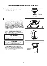
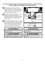
Страница 28: ...piezas Instale la clavija de horquilla y aseg rela con la pinza de horquilla Instale los set de tornillos con tuercas en el soporte de la varilla Fije con seguridad el set de tornillos con el destorni...
Страница 29: ...de la parte superior del barral Pele 1 2 cm 1 2 del aislamiento en cada extremo del cable Figura 7 C mo ensamblar el ventilador de techo cont Figura 8 Unidad del soporte de suspensi n 8 Extraiga una d...
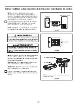
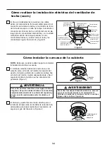
Страница 30: ...tier fusibles principal avant de suspendre le ventilateur afin d viter tout risque d lectrocution Figure 1 ADVERTENCIA La caja de distribuci n el ctrica de be estar bien asegurada y debe ser capaz de...
Страница 31: ...do que m s tarde se pueda realizar la instalaci n el ctrica 5 Fije el cable de seguridad al cable de soporte para techo Deslice la abrazadera de cables por el cable de seguridad del ventilador Pase el...
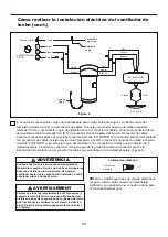
Страница 32: ...n a tierra para un funcionamiento seguro PRECAUCI N UNA CONEXI N INCORRECTA DEL CABLE PODR A DA AR ESTE RECEPTOR ATTENTION UNE CONNEXION DE FIL INCORRECTE PEUT ENDOMMAGER CE RECEPTEUR ADVERTENCIA Par...
Страница 33: ...conductor negro del ventilador con el conector de cables que se adjunta con la unidad receptora Finalmente conecte el conductor azul de la unidad receptora al conductor azul de la iluminaci n del ven...
Страница 34: ...es sont compl tement l int rieur du bo tier de la monture et qu ils ne sont pas pinc s entre le bo tier et le plafond AVERTISSEMENT Capuch n de techo Cubierta para el tornillo del capuch n Figura 2 Fi...
Страница 35: ...le ventilateur n est pas compl tement install L installation du ventilateur avec les pales assembl es peut endommager les pales du ventilateur Figura 2 Soporte de aspas 1 4 20 tornillo de cabeza 2 por...
Страница 36: ...5 5 Para su uso con el kit de iluminaci n B Instale la unidad LED en la unidad del kit de iluminaci n usando los tornillos extra dos en el paso 5 Figura 5 Ensamble de la placa de iluminaci n Kit LED...
Страница 37: ...unidad LED del kit LED extrayendo los tres tornillos Figura 7 Kit LED Kit LED Vidrio Unidad de luz LED C mo ensamblar su el kit de iluminaci n o la tapa cont Figura 9 8 Para su uso con la tapa de acer...
Страница 38: ...tores de cables con la excepci n del cable de toma de tierra No utilice el ventilador hasta que las palas est n colocadas en su lugar ya que de lo contrario se podr a causar ruido y da os 4 Para confi...
Страница 39: ...r de techo cont NOTA El mando a distancia incluido en este ventilador tiene 32 combinaciones diferentes de c digos Para evitar posibles interferencias desde o hacia otros mandos a distancia modifique...
Страница 40: ...deben evitarse para prevenir da os en el acabado Se recomienda limpiar el polvo de las aspas peri dicamente Lo mejor es utilizar un plumero Evite usar agua productos de limpieza o trapos speros que p...
Страница 41: ...es Escoja un m todo de control alternativo 5 Ruido del motor provocado por el control de velocidad de estado s lido variable 4 Aseg rese de que los soportes de las aspas del ventilador est n colocados...
Страница 42: ...t de cable de seguridad Lista de piezas Modelo N FP8003B N de Ref Descripci n Pieza N Antes de desechar los materiales de embalaje aseg rese de haber extra do todas las piezas Inserte los C DIGOS DE A...
Страница 43: ...Benito v2 Modelo FP8003B Ilustraci n del despiece NOTA La ilustraci n que se muestra no est hecha a escala y su c guraci n real y o terminaci n puede variar 16 1 2 3 4 5 6 7 9 10 16 8 16 12 11 15 14...
Страница 44: ...Copyright 2021 Fanimation Visite nuestro sitio Web en www fanimation com 10983 Bennett Parkway Zionsville IN 46077 Llame sin cargo al 888 567 2055 FAX 866 482 5215 Desde fuera de los EE UU llame al 3...