


- 2 -
1.2. Specifications
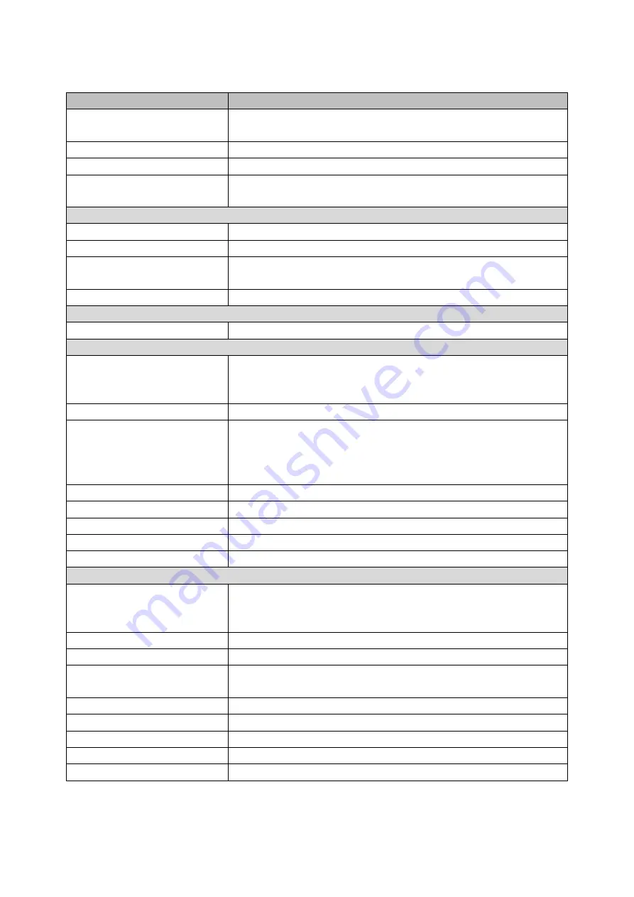
Model
AP-3515
CPU
Intel® Bay Trail-D Platform, Celeron® Processor J1900
2.0 GHz (2M Cache, up to 2.42 GHz)
System Memory
1 x DDR3L SO-DIMM Socket, up to 8GB
Graphic
Intel® HD Graphics
OS Support
POS Ready 7, Windows 7, Windows 8.1,
Windows 10 IOT Entry, Linux
Display
Screen Size
1
5” TFT LCD LED Backlight, (Ratio 4:3)
Resolution
1024 x 768
Touch Screen
True-Flat Projective Capacitive Touch (10 point)
True-Flat 5-wire Resistive Touch
Tilting Angle
15~85 degree
Storage
SATA II
1 x 2.5” SATA II HDD or SSD or m-SATA
Interface
Serial
4 x COM with RI/+5VDC/+12VDC output by BIOS,
(COM1~ COM3, setting in I/O Bracket,
COM4, USB Type A setting in Panel Side)
Parallel
1 x DB-25 Parallel Port (optional)
USB
6 x USB type A
(1 x USB 2.0 and 1 x USB 3.0 in I/O Bracket
2 x USB 2.0 in Base Side,
2 x USB 2.0 in Panel Side)
LAN
1 x RJ-45, Giga LAN Support (10/100/1000 Mbps)
VGA
1 x DB-15, Female (Max Resolution: 1920 x 1080)
Cash Drawer
1 x RJ-11, +12VDC/+24VDC by jumper select
DC Out
1 x +12VDC/5A power output
DC In
1 x +12VDC Standard Mini-DIN 4PIN type
Others
Power Adapter
+12V/5A, 60W External Power Adapter
with Cable Head Lock
(Power Adapter: 100VAC~240VAC, 50/60Hz)
Color
Black
Compliance
FCC/CE/LVD/RoHS
Weight
7.8 kg (without printer)
9.9 kg (with printer)
Dimension
355.3 (W) x 448.9 (H) x 248.6 (D) mm
Operating Temperature
0°C~40°C
Operating Humidity
20% ~ 80% RH non-condensing
Storage Temperature
-20°C~55°C
Storage Humidity
20% ~ 85% RH non-condensing
* The specifications are subjected to change without prior notice.


