background image

Shenzhen Hpmont Technology Co., Ltd. 

Chapter 6 Function Introduction 

HD3N-L Series User Manual V1.0 

-  29


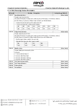
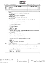
6.2.3


F02: Start and Stop Parameters


Ref. Code 

Function  Description 

Setting Range [Default] 

F02.00 

Start delay time 

0.000 - 4.999 [0.000s] 


Defines the delay time from the running command to the controller in the running state. 

• 

F00.05 = 0 (keypad control), F02.00 is invalid.   

F02.01 

Brake open delay time 

0.000 - 4.999 [0.500s] 

F02.02 

Start zero-speed hold time 

0.000 - 4.999 [0.000s] 


It defines the time from when the brake is opened to when there is speed output, and the motor has 
output torque during this period. 

• 

It can improve the comfort when starting. 

F02.03 

Start speed 

0.000 - 0.400 [0.030m/s] 

F02.04 

Start speed hold time 

0.000 - 4.999 [0.300s] 

F02.05 

Brake close delay time 

0.000 - 1.999 [0.300s] 


Defines the time from when the controller runs from zero speed to when the brake close command is 
output. 

F02.06 

Stop zero-speed hold time 

0.000 - 4.999 [0.300s] 


Defines the time to keep the motor at zero speed and output torque when stopping. 

• 

It can improve the comfort when parking. 

F02.07 

Run contactor close delay time 

0.000 - 4.999 [0.000s] 


Defines the delayed close time of the run contactor after the running command is cancelled. 

F02.08 

Starting ramp time 

0.001 - 2.000 [0.500s] 


It defines the time required for the elevator to accelerate from zero speed to the rated speed (F00.02). 

• 

Invalid when set to 0. 


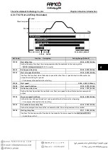
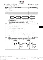
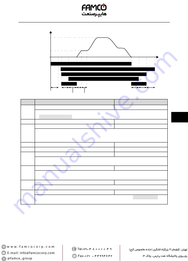
F02.00 F02.01

F02.08

F02.02 F02.04

F02.03

0

Contactor output
Controller running

Brake

Zero-speed

Zero-speed

F02.05F02.06F02.07

Run command

Speed

Time

Objective speed

Содержание Hpmont HD3N-L Series

Страница 1: ...product until you have fully understood safety precautions Note Preserve this Manual for future use If you need the User Manual due to damage loss or other reasons please contact the regional distrib...

Страница 2: ......

Страница 3: ...Version and Revision Records Time 2020 04 Version V1 0 Revised Chapter Revised Contents V1 0 publish...

Страница 4: ......

Страница 5: ...2 Peripheral Accessories Selection 11 4 2 1 Wiring Specifications of Input and Output 11 4 2 2 Power Terminal Lug 12 4 3 Main Circuit Terminals and Connection 12 4 4 Control Terminals and Connection...

Страница 6: ...p Parameters 35 6 2 10 F09 Current loop Parameters 36 6 2 11 F12 Digital I O Terminal Parameters 36 6 2 12 F13 Analogue I O Terminal Parameters 39 6 2 13 F14 SCI Communication Parameters 40 6 2 14 F15...

Страница 7: ...Chapter 8 Troubleshooting and Maintenance 57 8 1 Troubleshooting 57 8 2 Reset Fault 59 8 3 Maintenance 60 Appendix A Parameters 63 Appendix B Communication Protocol 77...

Страница 8: ......

Страница 9: ...n A Parameters Elevator Application Guidance 8 Troubleshooting and Maintenance 1 Safety Information 2 Product Information Machenical Installation B Communication Protocol 6 Function Introduction 5 Ope...

Страница 10: ......

Страница 11: ...choose the adaptive motor HD3N L can effectively implement thermal protection of motor Otherwise it must adjust the motor protection parameters or other protection measures to ensure that the motor i...

Страница 12: ...and the motor be sure to operate these circuit breakers or contactor when HD3N L has no output so as to avoid any damage to HD3N L Running Voltage HD3N L is prohibited to be used beyond the specified...

Страница 13: ...tsink efficiency will be reduced because of the tenuous air The rated value of output current derates by 1 for each 100m increase of the altitude I e for the altitude of 4000m derated rate is 30 for r...

Страница 14: ......

Страница 15: ...rrent A Rated Output Current A Size HD3N 4T7P5 L 7 5 11 19 17 Frame3 HD3N 4T011 L 11 16 28 25 Frame3 HD3N 4T015 L 15 21 35 32 Frame4 HD3N 4T018 L 18 5 24 39 37 Frame4 HD3N 4T022 L 22 30 47 45 Frame5 P...

Страница 16: ...n Achieve parameters uploading and downloading optional keypad Programmable input and output interface Input terminal function can be edited output terminal function can be edited Communication Standa...

Страница 17: ...ter vapor dripping water or salt etc Altitude Less than 1000 meters otherwise should be derating use Humidity Less than 95 RH non condensing Oscillation 3 5m s2 at 2 9Hz 10m s2 at 9 100Hz IEC60721 3 3...

Страница 18: ......

Страница 19: ...all at direct sunlight moisture water droplet location Do not install at flammable explosive corrosive gas and liquid location Do not install at oily dust fiber and metal powder location Be vertical i...

Страница 20: ...l HD3N L vertically and always provide the following space to allow normal heat dissipation The installation space mm is shown on the right figure 123 3 4 Dimensions and Weight Size Dimension mm Mount...

Страница 21: ...L For HD3N L with more than 2 year s storage please use regulator to power it slowly Do wiring connection of the braking resistor according to the wiring figure Make sure the terminals are fixed tight...

Страница 22: ...Torque N M 1 2 1 5 2 3 2 5 4 0 5 0 Max Outer Diameter d mm 10 2 12 3 17 0 123 4 3 Main Circuit Terminals and Connection The bare portions of the power cables must be bound with insulation tapes Ensure...

Страница 23: ...rminals and Connection The control circuit which is designed as ELV Extra Low Voltage circuit and power circuit are basically insulated Do not touch HD3N L after it is powered If the control circuit i...

Страница 24: ...on terminal SEL and P24 are connected by default Disconnect SEL and P24 when use external power to drive DI DO1 COM DO2 COM Digital output Programmable optical couple isolation open collector output O...

Страница 25: ...control cable should limit within 50m There should be more than 0 3m between the control cable and the motor cable The control cable must be shielded cable Figure 4 3 Control terminal connection DI1...

Страница 26: ...allation Shenzhen Hpmont Technology Co Ltd 16 HD3N L Series User Manual V1 0 4 5 Communication Terminal Terminal Description A 485 B 485 RJ45 Pin Definition 1 3 5V 2 485 4 6 GND 7 485 8 Unused Control...

Страница 27: ...n driving system the noise source can be controller braking unit and contactor Noise receiver can be automation equipment encoder and sensor etc The mechanical system is divided into different EMC are...

Страница 28: ...able clamps as shown in Figure 4 6 Figure 4 6 Shielded cable connection 4 6 3 Motor Connection The longer motor cable is the higher carrier frequency will be causing the high harmonic leakage current...

Страница 29: ...r through which lower frequency current can flow while higher frequency current can hardly flow Function of EMI filter 1 The EMI filter ensures the equipment not only satisfy the conducting emission a...

Страница 30: ...ttle affects the instruments outside the metal cabinet The cables are the main EMI source If connect the cables according to this manual the EMI can be suppressed effectively If the controller and oth...

Страница 31: ...us Displayed when the motor is forward REV Reverse status Displayed when the motor is reversed ALM Alarm status Displayed when there is a fault LO RE Remote or local status Displayed when the controll...

Страница 32: ...un state press standard or optional to display the stop or run state parameters in a loop Stop state parameters Setting speed DC bus voltage input terminal status Run state parameters Setting speed af...

Страница 33: ...ers pages 29 30 F03 Acc and Dec Parameter pages 31 31 F04 Analogue Curve Parameters pages 31 31 F05 Speed Parameters pages 31 32 F06 Optimize parameters pages 32 33 F07 Motor parameters pages 33 35 F0...

Страница 34: ...d Bit10 Unused Bit9 Contactor feedback input 0 Invalid 1 Valid Bit8 Brake feedback input 0 Invalid 1 Valid Bit7 Bit4 Unused marked as 0 Bit3 Analogue run 0 No 1 Yes Bit2 Multi speed run 0 No 1 Yes Bit...

Страница 35: ...ed Actual value D01 04 Setting frequency Actual value D01 05 Setting frequency after Acc and Dec Actual value D01 06 Output frequency Actual value D01 07 Setting RPM Actual value D01 08 Running RPM Ac...

Страница 36: ...DI8 DI7 DI16 DI5 DI4 DI3 DI2 DI1 123 D03 02 Output terminal status Actual value Display output terminal status Standard LCD display is hexadecimal number optional LCD display is 16 bit binary number E...

Страница 37: ...the motor parameters please refer to F07 06 At the same time set the vector control parameters group F08 to exert excellent vector control effect F00 02 Elevator rated speed 0 100 4 000 1 500m s F00 0...

Страница 38: ...he parameter can be changed depends on the user s password status and the actual running conditions of the controller 1 Restore to factory settings Except group F01 F07 00 F07 14 F15 00 F17 11 F17 27...

Страница 39: ...030m s F02 04 Start speed hold time 0 000 4 999 0 300s F02 05 Brake close delay time 0 000 1 999 0 300s Defines the time from when the controller runs from zero speed to when the brake close command...

Страница 40: ...lues are raised The S curve becomes slower when parameter values are decreased F03 06 Inspection Acc speed 0 020 9 999 0 200m s2 F03 07 Inspection Dec speed 0 020 9 999 1 000m s2 Defines the Acc and D...

Страница 41: ...cs as shown in the figure below 6 2 6 F05 Speed Parameters Ref Code Function Description Setting Range Default F05 00 Multi speed 0 0 000 F00 02 0 000m s F05 01 Multi speed 1 0 000 F00 02 0 000m s F05...

Страница 42: ...0 F05 18 Over speed detection time 0 0 2 0 0 2s When the actual elevator speed exceeds F05 17 and the duration time exceeds F05 18 HD3N L alarms E0032 fault motor over speed F05 18 0 HD3N L does not d...

Страница 43: ...In the process of static auto tuning the stator resistance F07 07 rotor resistance F07 08 and leakage inductance F07 09 will be written into F07 07 F07 08 and F07 09 automatically For mutual inductanc...

Страница 44: ...on coefficient when the magnetic flux is 50 75 120 F07 15 Motor torque boost 0 1 30 0 0 1 F07 16 Motor manual torque boost end point 0 1 50 0 F07 03 2 0 To compensate the torque drop at low frequency...

Страница 45: ...9999 500 F08 02 High speed ASR KP 1 9999 500 F08 03 High speed ASR KI 0 9999 500 F08 04 ASR PI swithcing frequency 1 0 00 50 00 10 00Hz F08 05 ASR PI swithcing frequency 2 0 00 50 00 15 00Hz F08 00 F...

Страница 46: ...m is prone to oscillation If F09 00 or F09 01 is too small it will affect the system torque output capability F09 04 ASR execution frequency 2 6 4k 123 6 2 11 F12 Digital I O Terminal Parameters Ref C...

Страница 47: ...or will do inspection running This signal when used together with UP DN No 2 or No 3 function command can control the elevator to go up or down during inspection 8 Emergency run input BAT If enabled e...

Страница 48: ...open or close the brake 7 8 FDT1 FDT2 Refer to F05 12 F05 13 9 Speed within signal FAR When output speed of the controller is within the FAR detect range F05 16 output indicator signal The indication...

Страница 49: ...x output speed 3 Output current 0 twice rated current of HD3N L 4 Output voltage 0 1 2 times rated voltage of HD3N L 5 Bus voltage 0 2 2 times rated voltage of HD3N L 6 AI input 0 10V Note 1 At up up...

Страница 50: ...ty ASCII F14 01 Baud rate 0 5 3 0 1200bps 1 2400bps 2 4800bps 3 9600bps 4 19200bps 5 38400bps F14 02 Local address 0 247 2 F14 02 0 it means broadcast address F14 03 Host PC response time 0 1000 0ms F...

Страница 51: ...rameter 1 0 30 4 F15 09 Set stop status parameter 2 0 30 14 F15 10 Set stop status parameter 3 0 30 16 F15 11 Set stop status parameter 4 0 30 26 F15 12 Set stop status parameter 5 0 30 27 F15 13 Set...

Страница 52: ...detection time 0 1 10 0 2 0s F16 07 Multi speed inspection 0 7 0 When the DI terminals are not enough the MS1 MS3 can achieve inspection run DI terminal INS No 7 function only need set F16 07 0 to ent...

Страница 53: ...7 07 can be set as 100 when the controller drives a motor of the same power class To protect the motor when the motor power is smaller than the standard matched power user needs to set proper F17 07 T...

Страница 54: ...ult interval F17 12 F17 19 record status parameters of the controller at the last fault F17 20 F17 27 record the type and interval per time of four faults before the latest The unit of interval is 0 1...

Страница 55: ...18 Inspection run frequency 0 00 21 00 6 66Hz F19 19 Emergency run frequency 0 00 F00 03 3 33Hz F19 20 Start run frequency 0 00 10 00 0 00Hz F19 44 SVC5 mode 0 1 1 0 Formal mode 1 Optimization mode F1...

Страница 56: ...brake time when emergency run 0 0 3 0 1 5s F19 67 Current search and torque limit when emergency run 40 0 200 0 100 0 F19 68 Torque boost when emergency run 0 1 30 0 2 0 F19 69 Torque boost cut off p...

Страница 57: ...time 0 9 0s 0 Keep open 1 9 After the directional signal contactor opens for F20 03 the output contactor is closed after the enable signal is still invalid F20 04 Ground detection before running 0 1 0...

Страница 58: ......

Страница 59: ...al wiring set the digital input and output function parameters group F12 4 Terminal MS running mode According to the actual requirement of elevator and the elevator controller set MS parameters group...

Страница 60: ...nd F03 07 inspection Dec speed Inspection Running 1 Observe the running direction of the motor and confirm that it is consistent with the required running direction If it is inconsistent set F00 08 ru...

Страница 61: ...ction running is controlled by inspection MS command of elevator controller and the running speed is obtained by speed combination of MS terminal Control Part Connection Figure 7 2 Terminal MS running...

Страница 62: ...eed 0 700m s2 Set according to the elevator speed and running effect F03 01 Start Acc jerk 0 350m s3 F03 02 End Acc jerk 0 600m s3 F03 03 Dec speed 0 700m s2 F03 04 Start Dec jerk 0 600m s3 F03 05 End...

Страница 63: ...general function The terminal analogue special function setting content is shown as Table 7 3 Table 7 3 Terminal analogue run parameter Ref Code Function Value Remark F00 05 Operating mode 1 Terminal...

Страница 64: ...e of line 1 Max setting 100 0 F12 01 DI1 function 1 Controller enabled EN F12 02 DI2 function 2 UP F12 03 DI3 function 3 DN F12 15 DO1 function 2 Running F12 16 DO2 function 3 Zero speed running F12 1...

Страница 65: ...he run contactor and open the brake Acc at the line rate of F03 08 emergency Acc speed till the speed of F05 09 emergency run speed 3 When the elevator runs near a leveling area the elevator controlle...

Страница 66: ......

Страница 67: ...short Connect HD3N L and motor properly Set correct motor parameters Select controller with higher rating Set proper Acc time and Dec time E0002 Controller output Dec overcurrent E0003 Controller outp...

Страница 68: ...supply voltage is too low Overload protection factor of motor is not set properly Motor locked rotor or overload Adjust V f curve Check the power input Properly set the overload protection factor of m...

Страница 69: ...ot well connected Communication setting error Communication data error Check the connection Check the connection Correctly set the communication format and the baud rate Send the data according to Mod...

Страница 70: ...he indicators on the keypad are off and the voltage between power terminals and is below 36V For HD3N L with more than 2 years storage please use voltage regulator to increase the input voltage gradua...

Страница 71: ...power to the controller use a voltage regulator to gradually raise the input voltage to rated input voltage at least 5 hours Replacing Damaged Parts The components that are easily damaged are Cooling...

Страница 72: ......

Страница 73: ...0 00 9 99 Actual D00 03 Keypad Software version 0 00 9 99 Actual D00 04 Elevator running status The standard LCD display is hexadecimal number and the optional LCD display is a 16 bit binary number Bi...

Страница 74: ...ltage 0 999V Actual D02 Analogue Status Display Parameters on pages 26 26 D02 00 AI voltage 0 00 10 00V Actual D02 01 AI voltage after calculating 0 00 10 00V Actual D02 08 AO output 0 00 10 00V Actua...

Страница 75: ...s 28 29 F01 00 User s password 0 65535 0 1 F01 01 Menu mode 0 Full menu mode 1 Checking menu mode 0 1 F01 02 Function parameter initialization 0 No operation 1 Restore to factory settings 2 Download t...

Страница 76: ...tuning Dec speed 0 020 9 999m s2 0 100m s2 0 001m s2 F03 12 Stop Dec jerk 0 020 9 999m s2 0 350m s2 0 001m s2 F04 Analogue Curve Parameters on pages 31 31 F04 00 Setting curve 0 Line 1 1 Line 2 0 1 F...

Страница 77: ...01 Motor rated voltage 0V controller rated voltage Depend on HD3N L 1V F07 02 Motor rated current 0 0 999 9A 0 1A F07 03 Motor rated frequency 1 00 100 00Hz 50 00Hz 0 01Hz F07 04 Motor rated RPM 1 24...

Страница 78: ...cing frequency 1 0 00 50 00Hz 10 00Hz 0 01Hz F08 05 ASR PI swithcing frequency 2 0 00 50 00Hz 15 00Hz 0 01Hz F08 06 ASR integral limitation 0 0 200 0 F07 02 180 0 0 1 F08 07 ASR differential time 0 00...

Страница 79: ...ler is ready 2 Running RUN 3 Zero speed running 4 Zero speed 5 Run contactor output control 6 Brake output control 7 FDT1 8 FDT2 9 Speed within signal FAR 10 Up signal output 11 Down signal output 12...

Страница 80: ...arameter on pages 40 41 F14 00 Data format 0 1 8 2 format no parity RTU 1 1 8 1 format even parity RTU 2 1 8 1 format odd parity RTU 3 1 7 2 format no parity ASCII 4 1 7 1 format even parity ASCII 5 1...

Страница 81: ...atus parameter 4 26 1 F15 12 Set stop status parameter 5 27 1 F15 13 Set stop status parameter 6 0 1 F16 Function boost Parameters on pages 42 43 F16 00 Zero speed running signal delay time 0 00 10 00...

Страница 82: ...f lack of output 0 0 20 0s 0 0 Not detect 4 0s 0 1s F17 07 Motor overload protect factor 20 0 110 0 100 0 0 1 F17 08 Fault auto reset times 0 100 0 No auto reset function 0 1 F17 09 Fault auto reset i...

Страница 83: ...036 can t auto reset 0 1 F17 12 Setting freqency at NO 5 fault 0 00 100 00Hz 0 00Hz 0 01Hz F17 13 Output frequency at NO 5 fault 0 00 100 00Hz 0 00Hz 0 01Hz F17 14 DC bus vlotage at NO 5 fault 0 999V...

Страница 84: ...0Hz 0 01Hz F19 13 Multi speed frequency 3 0 00Hz F00 03 0 00Hz 0 01Hz F19 14 Multi speed frequency 4 0 00Hz F00 03 0 00Hz 0 01Hz F19 15 Multi speed frequency 5 0 00Hz F00 03 0 00Hz 0 01Hz F19 16 Multi...

Страница 85: ...tart DC brake time when emergency run 0 0 3 0s 0 0s 0 1s F19 65 Stop DC current when emergency run 50 100 70 1 F19 66 Stop DC brake time when emergency run 0 0 3 0s 1 5s 0 1s F19 67 Current search and...

Страница 86: ...ke open frequency 0 00 10 00Hz 0 00Hz 0 01Hz F20 06 Brake open current 0 150 0 1 F20 07 Restore customized parameters 0 9 0 1 F20 13 Emergency run torque limit 70 0 200 0 0 0 0 1 F20 14 Emergency run...

Страница 87: ...us parameters and write the control command etc The controller is in slave mode when it is communicating Communication Terminal For the communication terminals see section 4 5 page 16 The transmitting...

Страница 88: ...will be sent via ASCII code except frame head and frame tail higher 4 byte prior to lower 4 byte at sending Data is 7 byte and for the A F will adopt their uppercase of the ASCII code The data adopts...

Страница 89: ...CRC LRC Checking Data frame bytes 1 1 2 2 2 1 Value or range 0 247 0x03 0x0000 0xFFFF 0x0001 0x0004 Command Frame Address Code Starting Register Address No of Register CRC LRC Checking Data frame byt...

Страница 90: ...f controller etc the controller will start to save from low address to high address of the register when it continuously saves many register parameters The saving will return from the firstly failed a...

Страница 91: ...x32 Address Mapping The group number 0x32 of control parameter is mapped to the high byte of the register address and the intergroup indexes are shown as below table Address Function Save at Power Fai...

Страница 92: ...ller 0 Reset is invalid Bit7 1 Unused 0 This frame is mainly set as speed command The main setting of this frame is speed command Bit8 Bit11 0 Unused Bit12 1 Inspection run is valid Inspection run mod...

Страница 93: ...x3306 Controller status 0x3319 AI voltage after calculating 0x3307 Control mode 0x3320 AO output 0x3308 Setting speed 0x3323 Input terminal status 0x3309 Setting speed after Acc and Dec 0x3324 Output...

Страница 94: ...The code to calculate the CRC online is as follows unsigned int crc_check unsigned char data unsigned char length int i unsigned crc_result 0xffff while length crc_result data for i 0 i 8 i If crc_res...

Страница 95: ...egister Content Checksum 0x02 0x43 0x32 0x00 0x00 0x02 0x04 0x00 0x1F 0x00 0x02 0xF2 0xC3 Respon se Add Code Register Address Operate Register Number Checksum 0x02 0x43 0x32 0x00 0x00 0x02 0xCB 0x4F 3...

Отзывы: