Appoggiare alla parete il supporto mensola (A-Fig.2),ad un'altezza
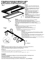
Phase 1
Loosen the 2 screws (A-Fig.1) below the
MONTAGEANLEITUGEN KONSOLE LUMEN
B
B
B
B
LUMENS SHELF ASSEMBLY INSTRUCTIONS
ISTRUZIONI DI MONTAGGIO MENSOLA LUMEN
bottom panel and pull out the panel.
Remove the 4 screws completely (B-Fig.1)
and pull out the shelf support (A-Fig.2).
dal piano determinata dalla somma delle quote X+20mm.
relative viti.
Forare,inserire n°4 tasselli ad espansione ø 8mm e fissare il supporto con le
punti di foratura alle estremità del supporto e n°2 punti più interni.
Controllare con una bolla di livello l'allineamento orizzontale e segnare n°2
Riposizionare il pannello inferiore e bloccarlo con le 2 viti (A-Fig.1).
Fig.2
Eseguire l'allineamento della mensola,bloccare definitivamente le 4 viti (B-Fig.1).
Inserire la mensola sul supporto,e fissarla con le 4 viti (B-Fig.1) senza bloccarle definitivamente.
Fase 3
Fase 2
Schritt 1
Die zwei Schrauben (A-Fig.1), die unter dem
unteren Paneel positioniert sind, ausdrehen
und das Paneel entfernen.
Die 4 Schrauben entfernen (B-Fig.1) und die
Konsolenhalterung herausziehen (A-Fig.2).
ed estrarre il supporto mensola (A-Fig.2).
A
A
A
A
A
A
A
A
Fase 1
Svitare le 2 viti (A-Fig.1) posizionate sotto
il pannello inferiore e rimuovere il pannello
stesso.
Rimuovere completamente le 4viti (B-Fig.1)
Fig.1
B
B
B
B
20
X
≥
650mm
A
Phase 2
Place the shelf support (A-Fig.2) next to the wall, at a distance from the top
corresponding to the sum of distance X+20mm.
With the help of a bubble level check that the shelf support
is horizontal. Mark 2 drilling holes at the ends of the shelf support and
2 internal holes.
Drill the holes, insert 4 expansion dowels (ø 8mm ) and secure the
shelf support to the wall with the relevant screws.
P h a s e 3
F it th e s h e lf o n th e s u p p o rt a n d s e c u re it w ith th e 4 s c re w s (B -F ig .1 ) w ith o u t tig h te n in g th e m .
A lig n th e s h e lf a n d th e n tig h te n th e 4 s c re w s (B -F ig .1 ).
F it th e b o tto m p a n e l a n d s e c u re it w ith
th e 2 s c re w s s u p p lie d (A – F ig .1 )
Schritt 3
Die Konsole in die Halterung einfügen und mit den 4 Schrauben (B-Fig.1) befestigen, ohne
diese ganz anzuziehen.
Die Konsole ausrichten und die 4 Schrauben fest anziehen (B-Fig.1).
Das untere Paneel wieder anbringen und mit den 2 Schrauben
(A – Fig.1) befestigen.
Schritt 2
Die Konsolenhalterung (A-Fig.2) an die Wand positionieren und dabei
eine Höhe von der Arbeitsplatte wählen, die sich aus der Summe der
Maße X+20mm ergibt.
Mit einem Nivellierinstrument die waagrechte Ausrichtung prüfen. An den
Enden der Konsolenhalterung 2 Bohrungen und 2 Bohrungen an der
Innenseite kennzeichnen.
Bohren, 4 Expansionsdübel
∅
8 mm einfügen und die Konsolenhalterung
mit den entsprechenden Schrauben befestigen.

