

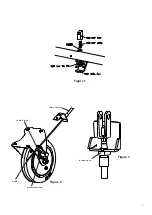

3.9 BRAKE MECHANISM
Refer to
Figures 2 and 3
.
(Page 7)
To adjust tension on brake cable:
Remove lower control panel below brake handle.
Use nut on underside to adjust to required tension.
Replace in reverse order.
If further adjustment is required:
Loosen brake cable terminal at castor.
Pull cable tight.
Re-tighten cable terminal.
Replace in reverse order.
To replace cable:
Cut off cable nipple.
Loosen cable terminal.
Pull cable free from sheath.
Replace in reverse order.
3.10 CASTORS
Note
: This unit is heavy.
Note
: Refer to Section 1.1 for nett weights. Take due care
when replacing castors. Unit may be jacked up or lifted
upon blocks to allow safe removal of castor(s).
Alternatively, an empty trolley may be laid on its back
provided appropriate lifting assistance is available to do
this in a safe and controlled manner.
Note
: Always replace castor with correct specification
variant for the given position.
To remove Castor
: Undo fixings on underside of trolley
to remove. Refit in reverse order.
To remove Castor with Brake: Loosen tension of cable
before release from castor brake mechanism. Replace in
reverse order.
To set brake tension, tighten turnbuckle to top and relase
by a half turn. Lock in place with nut. Regrease mecha-
nism at handle bar and castor. When trolley is resting on
all castors, ensures brake operates smoothly. It should
not be possible to move trolley when hand levers are re-
leased. Adjust screw link if necessary. Re-fit side panel
when satisfied brake operates correctly.
3.11 DOOR
To remove door, undo top door hinge fixings. Swing door
open and lift off bottom hinge.
To remove door catch roller bar assembly, undo locknut
to remove securing pin and roller.
Re-fit in reverse order. Check door operates as required.
3.12 DOOR with DOOR SEAL
Remove door as detailed in Section 3.11.
To remove door seal, undo fixings on inner door panel.
When refitting seal, start at bottom of door. Fit in stages
while securing inner panel. Make triangular cuts into seal
flange to form bends at corners. Apply sealant at
seal joint.
3.13 CHAMBER DOOR SEAL
Use a Ø4.5mm drill to remove aluminium rivets.
Re-use metal strips and rivet replacement seal to
chamber.
3.14 DUMMY SOCKET
Loosen mains power cable arrester. Remove side panel
fixings as Section 3.1 and open panel. Take care not to
put strain on power cable.
To remove socket, depress assembly fixing tabs and
withdraw through stiffening plate and panel.
Re-fit in reverse order, making sure stiffening plate is
fitted. Ensure cable arrest is effective.
SECTION 4 - SPARES
When ordering spare parts, always quote unit type and
serial number. This information can be found on
appliance data plate located upon appliance rear panel.
6