background image

14 

6.3   

GAS SUPPLY & CONNECTION 


6.3.1  Installation pipe  work should be fitted in accordance with local / national  standards. 

The 

pipe  work  must  not  be  smaller  than  unit  gas  inlet  connection,  i.e.    Rp¾  (¾” 

B.S.P.).  If  using  flexible  hosing,  the  hose  must  be  sized  to  conform  with  the  hose 
manufacturers specifications and the length must not exceed 1.5m. An isolating valve 
must be located close by for shut-down during an emergency or servicing. 


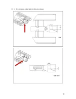
6.3.2  If  flexible  hose  is  used,  it  shall  comply  with  national  requirements.  These  must  be 

periodically  examined  and  replaced  as  necessary.  If  a  retention  chain  is  required 
then attach this to the fixing shown below. 


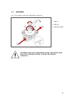
6.3.3  Supplied governor must be fitted to the rear of the appliance. (see 8.6) 


6.3.4  This  appliance  is  also  provided  with  a  terminal  for  connection  of  an  external 

equipotential  conductor.  This  terminal  is  in  effective  electrical  contact  with  all  fixed 
exposed  metal  parts  of  the  appliance,  and  shall  allow  the  connection  of  conductor 
having a nominal cross-section area of up to 10mm². It is located at the rear of the 
unit and identified by the following label and must only be used for bonding purposes. 


Содержание G9440

Страница 1: ...r installation and servicing instructions GAS CHARGRILL G9440 G9460 G9490 G94120 Read these instructions before use T100873 DATE PURCHASED MODEL NUMBER SERIAL NUMBER DEALER SERVICE PROVIDER REV 4 Publ...

Страница 2: ...iance and any replacement parts in a safe manner via a licensed waste handler Appliances are designed to be dismantled easily and recycling of all material is encouraged whenever practicable Dear Cust...

Страница 3: ...3 SYMBOLS SPANNER SCREWDRIVER COOKING OIL GREASE SPARK IGNITION FLAME WARNING VIEWPORT ALLEN KEY IGNITER...

Страница 4: ...d persons The installer must instruct the responsible person s of the correct operation and maintenance of the appliance Only competent persons are allowed to service or convert the appliance to anoth...

Страница 5: ...N LOCATIONS 12 6 0 INSTALLATION 13 6 1 SITING CLEARANCES 13 6 2 VENTILATION 13 6 3 GAS SUPPLY CONNECTION 14 6 4 ASSEMBLY 15 6 5 COMMISSIONING 15 6 6 SUITING 16 7 CONVERSION 18 7 4 GAS CONVERSION CHECK...

Страница 6: ...elevant EU directives for the heat inputs gas pressures and voltages stated on the data plate A Serial No B Model No C Flue Type D Gas Category E Gas Pressure F Gas Type G Gas Rate H Total Heat Input...

Страница 7: ...PONENT PARTS A Scraper B Lifting Tool C Brander Bar D Burner Baffle E Splashguard F Burner G Control Knob H Spark Igniter I Drip Tray J Deflector K Fat Jug Not required in G9440 2 2 CONTROLS A Spark I...

Страница 8: ...nd out See section 3 2 3 2 Position burner baffles and brander bars correctly A High position B Low position C Burner Baffle D Baffle support E Lightly oil bars 2 3 3 Fill about a 1 3 of the drip tray...

Страница 9: ...ars 3 3 Scrape off burnt on food 3 4 Remove other debris using a cloth 3 5 Dry and brush with vegetable oil 3 6 Remove splashguard burner baffles and fat jug and clean 3 7 Wipe burners with a damp clo...

Страница 10: ...5 Amal 300 Amal 300 G94120 2 5 Amal 310 Amal 310 Pilot Injectors 31 2 25 25 Supply Pressure mbar 20 29 50 37 Operating Pressure mbar 15 29 37 HEAT INPUTS kW G20 G30 G31 Full Low Full Low Full Low G94...

Страница 11: ...11...

Страница 12: ...12 5 0 DIMENSIONS CONNECTION LOCATIONS A GAS INLET...

Страница 13: ...IONS 6 2 VENTILATION This appliance must be installed with sufficient ventilation to prevent the occurrence of unacceptable concentrations of substances harmful to health in the room in which they are...

Страница 14: ...mply with national requirements These must be periodically examined and replaced as necessary If a retention chain is required then attach this to the fixing shown below 6 3 3 Supplied governor must b...

Страница 15: ...e 8 6 for governor adjustment 6 5 3 Light all pilots and ensure all stay lit 6 5 4 Turn on main burners Ensure correct cross lighting occurs 6 5 5 Check for flame stability 6 5 6 Operate taps between...

Страница 16: ...e hob rear infill and replace with rear suiting plate and fixings 6 6 4 Remove the front side panel countersunk screw and suiting plate NOTE The DLS system is designed to give a quick and easy suiting...

Страница 17: ...through the front fixing holes of both units 6 6 8 B Left hand unit Slide the penny and lock washer on to the screw and secure using the M5 nut 6 6 9 C Remove the front bolts from feet insert base ti...

Страница 18: ...by turning screw fully clockwise To convert back to Ng ensure screw is turned fully clockwise and then turn screw two complete turns anti clockwise see 8 5 As a reference the flame on turndown should...

Страница 19: ...19 8 SERVICING 8 1 BURNERS 8 1 1 Remove burners as shown 8 1 2 Clean burners see section 3 8 1 3 Clean ports...

Страница 20: ...20 8 1 4 For conversion adjust aeration shroud as shown...

Страница 21: ...ner ensure locating lugs locate in the rear support bar correctly 8 2 INJECTORS 8 2 1 Remove injector as shown 8 2 2 Clean injector 8 2 3 Check washers are clean and serviceable 8 2 4 After replacemen...

Страница 22: ...22 8 3 CONTROL PANEL 8 3 1 Remove as shown 8 4 PILOT ASSEMBLY 8 4 1 Remove pilot components as shown A Thermocouple B Pilot gas pipe C Spark electrode D Pilot bracket...

Страница 23: ...23 8 5 GAS VALVE 8 5 1 Remove gas valve as shown A Thermocouple B Pilot gas pipe C Main gas pipe D Valve clamp E Bypass screw 8 5 2 Service valve as shown...

Страница 24: ...VERNOR 8 6 1 This applies to G20 and G30 50mb models only 1 Gas in 2 Gas out 3 Direction of flow GOVERNOR SUPPLIED IS MAINTENANCE FREE ENSURE THE BLUE DUST CAP COVERING THE VENT IS FITTED AND IN GOOD...

Страница 25: ...t Gas pressure too low Check pressure adjust as necessary Injector s blocked or damaged Clear nozzle s or replace Burner ports blocked Clear ports or replace Gas tap s seized or blocked Clear or repla...

Страница 26: ...mber Serial number Gas Type This information is found on data plate on front panel See section 1 0 Visit our website for further spares information 11 SERVICE INFORMATION It is recommended to have a m...

Отзывы: