background image

Installation & User Manual                                                                               Falcon Electric, Inc.                                                                                                                                    

FN2 Series OM480051 Rev.: E                                                                                                                                          

17                                                                                                                                                                                                                                                                                      

                   Getting Started 

Installation  


This UPS must be installed in a clean environment, free from moisture, liquids, 

flammable gases 

or fumes and corrosive substances. Operate the UPS in an indoor environment within the 

temperature range of 0ºC to 40ºC (32ºF to 104ºF) To maximize battery life, a temperature range 

of 20ºC to 25ºC (68ºF to 77ºF) is ideal. 


This UPS is 

designed for use with industrial, scientific or data processing class equipment.


(PCs, workstations, servers etc.) 


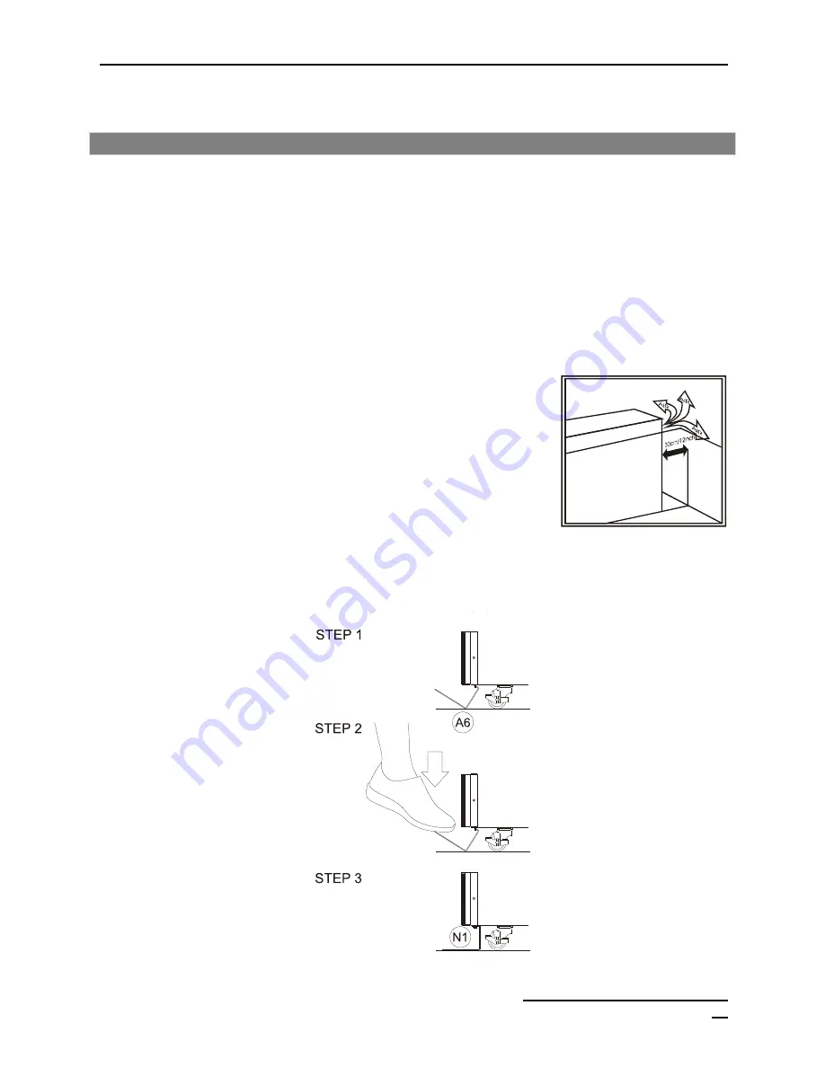
The system air flow is from front to rear. 


Please follow these instructions: 


1.  Keep at least 12 inches (30.5cm) clearance from the rear 

panel of the UPS to the wall. 


2.  Do not block the air flow to the ventilation openings of the 

unit. 


3.  Ensure that the installation site is clear and allows enough 

workspace to access UPS. 


Accessory Installation  


Содержание FN2-4.5K-2TXI

Страница 1: ...con Electric logo are registered trademarks of Falcon Electric Inc All other brand names and trademarks are the property of their respective owners The information and specifications stated in this do...

Страница 2: ......

Страница 3: ...Rear Panel 14 Communication Port 15 LCD Display Icons 16 Getting Started 17 Installation 17 UPS Input Terminal Block 18 UPS Output Terminal Block 19 Internal UPS Transformer Schematic 22 Internal UPS...

Страница 4: ...tion User Manual Falcon Electric Inc FN2 Series OM480051 Rev E 4 N 1 Parallel Operation 41 Constant Frequency Operation 42 Specifications 43 Electrical 43 Service Warranty 44 Technical Support 44 Warr...

Страница 5: ...o unpack install or operate this UPS Warnings When replacing batteries replace with the same number of the following battery NP7 2 12 7Ah or NPW45 12 9Ah CAUTION Risk of Energy Hazard 12V 7 or 12V 9 A...

Страница 6: ...es for 4 5 to 6kVA rating or 50 amperes for 8 to 10kVA rating in accordance with the National Electric Code ANSI NFPA 70 CAUTION To reduce the risk of fire connect the UPS only to a circuit provided w...

Страница 7: ...batteries Please retain the shipping container in the unlikely event the UPS needs to be returned for service The container has been specifically designed to ship the UPS safely Storage If the UPS is...

Страница 8: ...minants Avoid direct sunlight Do not install the UPS in a flammable or otherwise hazardous environment Avoid vibration and areas subject to physical impact To prevent overheating keep all ventilation...

Страница 9: ...res as well as detailed operation and configuration of this device UPS Features True on line architecture continuously supplies your critical device with stable regulated transient free pure sine wave...

Страница 10: ...mal the DC boost will increase the DC voltage to an acceptable level for the inverter i Battery Fuse Over current protection for the batteries j Charger Two stage constant current constant voltage cha...

Страница 11: ...ediately le a claim for shipping damage with the carrier If you discover damage after acceptance le a claim for concealed damage To le a claim for shipping damage or concealed damage YOU MUST le with...

Страница 12: ...Installation User Manual Falcon Electric Inc FN2 Series OM480051 Rev E 12 Accessories Kit...

Страница 13: ...is within the acceptable window Flashing green LED indicates that the utility input voltage is outside the acceptable window 4 Green LED indicates the bypass input is normal 5 UPS On Alarm Silence but...

Страница 14: ...ot 1 Channel A F Cooling Fan G External Battery Connector I Utility Input Breaker CB1 J Bypass Input Breaker CB2 Dual input model only K Maintenance Bypass Switch L Input Output Terminal Block M Mount...

Страница 15: ...tely monitor the power and UPS status The software bundled with the UPS is compatible with many operating systems such as Windows 2000 XP Server 2003 VISTA Server 2008 Windows 7 and Windows 10 For oth...

Страница 16: ...o transfer to bypass Bypass abnormal at ECO mode 2 Utility input abnormal 3 Not Used 4 Alarm Silent 5 UPS Output overload 6 Not Used 7 UPS Alarm 8 3 Digit Measurement 8a EPO Emergency Power Off 8b OFF...

Страница 17: ...mize battery life a temperature range of 20 C to 25 C 68 F to 77 F is ideal This UPS is designed for use with industrial scienti c or data processing class equipment PCs workstations servers etc The s...

Страница 18: ...on Electric Inc FN2 Series OM480051 Rev E 18 UPS Input Terminal Block Input Configuration Table Terminal 1 Terminal 2 Terminal 3 Terminal 4 G1 N1 L12 L11 Utility Ground Utility Neutral L2 Utility Line...

Страница 19: ...2 Terminal 3 Terminal 4 Terminal 5 Terminal 6 G2 N22 N11 L22 L11 L12 Ground 0V 0V 120V 120V 88V N L2 Jumper N11 to L22 Not Used L L1 240V Output Output Configuration Table 240V Terminal 1 Terminal 2...

Страница 20: ...120V 120V 88V Jumper to N11 L2 Jumper N11 L22 G2 Neutral Not Used L1 The 120Vac output must not be loaded more than 50 of maximum rated UPS output capacity 240V 120V Output Output Configuration Table...

Страница 21: ...terminals For 120Vac output only application output terminal N22 must use AWG 8 wire connected to ground Neutral Bonding AC Input Output Current and Wire Recommendation Model Maximum Current Conductor...

Страница 22: ...Internal UPS Transformer Schematic 0V 208V 240V 0V 120V 120V 88V 0V UPS Load Internal UPS Transformer Configurations 0V 208V 240V 0V 120V 120V 88V 0V UPS Load 240V 120V 208V 120V 0V 208V 240V 0V 120V...

Страница 23: ...inputs are normal UPSs with parallel function enabled will display figure A1 then figure A2 and then figure B Otherwise the LCD will display figure A1 directly followed by figure B A1 A2 B 3 The UPS i...

Страница 24: ...roximately four seconds Then the display will change from figure E1 to figure F if the self test was successful D E1 F 6 If the self test fails the LCD display will change from figure D to figure E2 t...

Страница 25: ...displays figure I In case of failure of cold start procedure the UPS will automatically turn off You must then repeat step 1 G H I 2 Check measured values and figures detected by the UPS a If you woul...

Страница 26: ...Installation User Manual Falcon Electric Inc FN2 Series OM480051 Rev E 26 I1 J K L M N...

Страница 27: ...Installation User Manual Falcon Electric Inc FN2 Series OM480051 Rev E 27 O O1 P O2...

Страница 28: ...1 Q2 2 Press the Next Page button to scroll through the UPS settings The LCD will display in sequence figure Q1 buzzer figure R1 Self test figure S1 Bypass Voltage Windows figure T Output Frequency Sy...

Страница 29: ...Installation User Manual Falcon Electric Inc FN2 Series OM480051 Rev E 29 S2 T U V1 V2 V3...

Страница 30: ...Make sure the UPS is in Bypass Mode Press the on and Next Page buttons simultaneously for approximately three seconds The buzzer will sound twice and the LCD will display figure Q1 indicating that the...

Страница 31: ...d ON separately indicate disabled and enabled h Figure Z indicates the last page of settable parameters i After changing settings you must press the Enter button to save all your changes and exit the...

Страница 32: ...NCE BYPASS SWITCH FAILURE TO FOLLOW THIS PROCEDURE WILL RESULT IN DAMAGE TO THE UPS OR CONNECTED EQUIPMENT 8 Press the Off button for approximately 5 seconds UPS will emit 2 beeps a UPS is in Bypass M...

Страница 33: ...except both Bypass indicators LED and LCD and Utility indicators LED and LCD If the Bypass or Utility is abnormal after the UPS is locked the related LED or will be off and the related LCD symbol or w...

Страница 34: ...cuit Er10 Inverter over current Er11 UPS over temperature Er12 Severe UPS output overload Er14 Fan error Er16 Output parameters set error in parallel system Er17 ID Numbers are in conflict in Parallel...

Страница 35: ...ove the short circuit at the EPO terminal then restart UPS Er11 Er33 Remove any objects blocking the ventilation holes Er14 Replace cooling fan Er15 If UPS is in CVCF mode you must restart the UPS Er1...

Страница 36: ...e battery life Connect and turn on UPS to a properly rated outlet for at least 12 hours to ensure batteries are in a fully charged state prior to long term storage o Always switch off the UPS when rel...

Страница 37: ...ery Service Life Float Trickle Charge The table below provides the typical battery service life during float trickle charge Ambient temperature greatly affects the overall battery life Temperature Per...

Страница 38: ...nstallation User Manual Falcon Electric Inc FN2 Series OM480051 Rev E 38 Battery Replacement REFERENCE SAFETY SECTION OF THIS MANUAL FOR ALL BATTERY SAFETY WARNINGS 4 5 to 6kVA Models 8 to 10kVA Model...

Страница 39: ...Installation User Manual Falcon Electric Inc FN2 Series OM480051 Rev E 39...

Страница 40: ...on Pin 9 Shutdown UPS positive signal Pin 10 Shutdown UPS negative signal Notes The shutdown function will be activated after 6 to 25 VDC is applied between pin 9 and pin 10 for 5 seconds The capacity...

Страница 41: ...led by the UPS output load monitoring During normal operation the load is shared equally among the total number of UPSs installed If the total connected load amount is equal to or less than the capaci...

Страница 42: ...that require a constant frequency for the applied load The output frequency will not be synched to the input frequency Notes This option requires Bypass Line to be disabled internally Please specify t...

Страница 43: ...Installation User Manual Falcon Electric Inc FN2 Series OM480051 Rev E 43 Specifications Electrical For latest released version please visit our website at falconups com...

Страница 44: ...artment determine service is required you will be given a Return Material Authorization RMA number along with return shipping instructions The RMA number issued must appear on the outside of the shipp...

Страница 45: ...r damage caused by i improper installation misuse or neglect ii unauthorized repairs or modifications or use of unauthorized parts iii acts or events outside of Falcon s control such as fire accidents...

Отзывы: