CHAPTER
CHAPTER
3
3
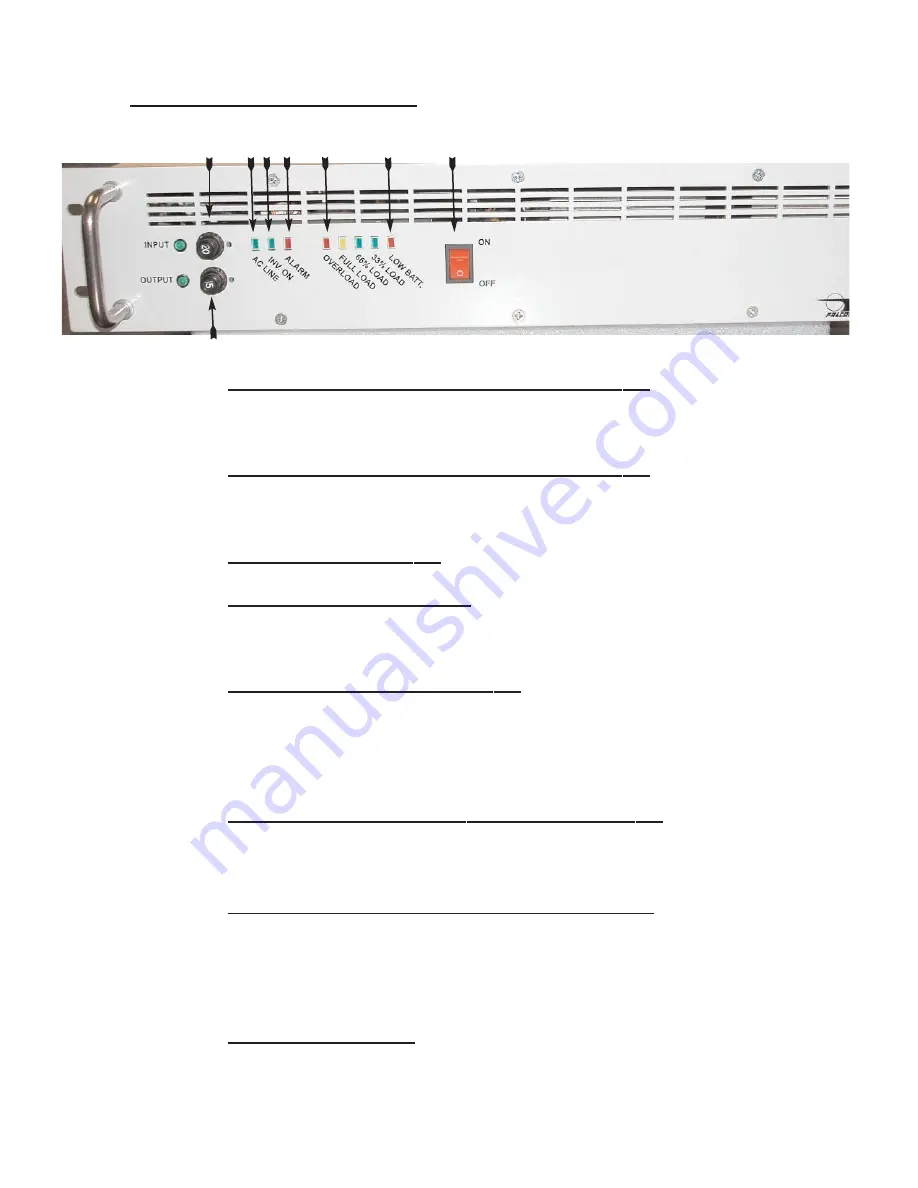
Controls, Displays & Functions
1.
INPUT POWER CIRCUIT BREAKER & INDICATOR
Pull button to remove input power. The UPS will go into battery mode
when pulled.
Push the button in to reset the circuit breaker.
2.
UPS OUTPUT CIRCUIT BREAKER & INFDICATOR
This circuit breaker provides overload protection for the UPS. Pull the
button to turn off the UPS output. Push the button to reset the circuit
breaker.
3.
AC- AC LINE INDICATOR
This green LED turns on when the utility AC is present.
4.
INV- INVERTER OPERATING
The LED turns green when the UPS inverter is turned on. This LED
normally turns on a few seconds after the AC line indicator LED and
remains on during both utility and battery operation.
5.
ALM- ALARM STATUS INDICATOR
This red LED turns on and a continuous audible alarm is sounded when
the UPS is overloaded or has failed. Should this occur, check the load
level and correct any overload condition if present. During this condition,
UPS load outlets will be powered by filtered utility bypass power.Should
the unit not be overloaded, call FALCON
®
support for further assistance..
6.
LOW BATT.- LOW BATTERY WARNING INDICATOR
The red LED will turn on when the UPS is operating in battery mode
and the low battery level warning point has be reached. Typically one
minute of battery runtime remains after the LED turns on.
7.
OVERLOAD/ FULL LOAD/ 75% LOAD/ 50% LOAD-
Adjacent to the red low battery LED is the green 50% load LED.
Adjacent to the green 50% load LED is the green 75% load LED.
Adjacent to the green 75% load LED is the yellow 100% load LED.
Adjacent to the yellow 100% LED is the red overload LED. All overload
conditions must be corrected immediately.
8.
UPS ON/OFF SWITCH
WARNING! Ths switch turns the UPS on and off. Turning this switch
to the off position will trun off power to the connected load.
1
2
3 4 5
7
6
8
6
NOTE: Reference page 10 for more details


