JP14-R-LP & JP14-Q-LP F
ALCOM
GPS R
ECEIVERS
V
ERSION
1.0.0
5.4 Power management modes overview
There are three basic operating modes in which the JP14 family operates during use.
Each mode is used to accomplish a different task during the process of acquiring
and maintaining the GPS information. The JP14 family include all the functionality
necessary to implement the three different modes of operation. By default, the JP14
family runs in normal mode (continuous mode). All three different operating modes
are described below. Additionally, two of them such as Adaptive TricklePower™
(ATP) and Push-to-Fix (PTF) are designed as power saving modes.
5.4.1 Normal Operation mode
In this default implementation of normal mode the JP14 family is fully powered and
performs the function of signal search, acquisition, measurement and satellite
tracking. The amount of time spent in the initial full power is dependent on the start
conditions such as the number of satellites for which the ephemeris data must be
collected and the time to calibrate the RTC. When the JP3 family has been locked-
on to at least four satellites, the receiver is able to calculate its current positions. In
this mode the JP14 family is fully powered and satellite searching, initial acquisition,
initial position calculation and tracking measurement functions are always
performed. In order to reduce the start up time of the receiver it is preferable to
connect externally a backup battery, so that the RTC is running during the power
interrupt. The backup power is required for retention of SRAM memory and
maintaining the Real-Time-Clock. The validity of data stored in SRAM is kept due to
RTC keeps running and these data will be needed on the next power up scenario.
5.4.2 Adaptive TricklePower mode (ATP)
Adaptive TricklePower (ATP) is a variant of TricklePower ™. But only ATP and Push-To-
Fix (PTF is described in next chapter) modes are supported on JP14 family. ATP is best
suited for applications where regular updates are required, and where stronger
signal levels are expected. The transition of receiver into the ATP mode can be done
and configured by using either the
Action│Set Low Power (Trickle Power) …
command available in SiRFDemo evaluation software or the input command
described in chapter
5.4.4
on page
17
.
When ATP is enabled the receiver will maximize the navigation performance.
Depending on different states of the power management circuits, the receiver
belongs to one of three system states:
Full Power State (Acquisition/Tracking modes)
After initial turn on or system reset, the JP14 will remain in the full power state until
a series of Kalman filter navigation solution is obtained, all ephemeris data is
collected and the RTC is calibrated before transitioning to CPU-state. The receiver
stays in full power state until a position solution is made and estimated to be
reliable. In this state all RF circuitry and the baseband are fully powered. Even in
this state, there is a difference in power consumption during acquisition mode
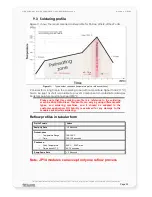
and tracking mode. During the acquisition mode, processing is more intense, thus
consuming more power (Diagram is shown below that is simplified for ease of
understanding. Timing values are only examples).
CPU-State
In this state the LNA in the RF section is shut off. The TCXO and fractional
synthesizer from the RF section are still powered in order to provide a clock to the
CPU. This state is entered when the satellite measurements have been collected
This confidential document is the property of FALCOM and may not be copied or circulated without permission.
Page 15

