


Description
GPS receiver
A2D–JP
Version 1.03
Side 23
6.2
Product overview
The GPS receiver requires conditioned 3,3 V DC power and a GPS
signal from a passive or active antenna.
The 12 channel architecture provides rapid Time-To-First-Fix
(TTFF) under all start-up conditions. As long as visible satellites are
not obscured, acquisition is guaranteed under all initialisation con-
ditions.
To minimise TTFF when main power is removed from the GPS re-
ceiver SRAM with external DC supply voltage and EEPROM are
used to archive RTC time and prior position data.
Communication with the GPS receiver is established through two
asynchronous serial I/O ports. The GPS receiver's primary serial
port outputs navigation data and accepts commands from OEM ap-
plication in NMEA-0183 format or CONEXANT binary format.
The secondary port is configured to accept differential GPS (DGPS)
corrections in the RTCM SC-104 format.
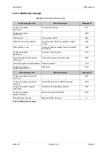
6.2.1 GPS receiver architecture
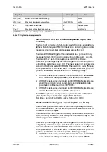
Figure 7: GPS receiver architecture
The functional architecture of the GPS receiver is shown in Figure 7.
The GPS receiver design is based on the Conexant Zodiac chip set,
the RF-Monopac and the Scorpio DSP, which contain the required
GPS functionality. The RF-Monopac contains all the RF down-con-
version and amplification circuitry, and presents the In-Phase (I) and
Quadrature-Phase (Q) Intermediate.
Содержание A2D-JP
Страница 1: ...Description Embedded GSM GPS Module A2D JP...


