


Q
uer
C
us SERCOS-II Drive System.
I
nstallation
G
uide. Ref.1801/B
QCIG-15/16
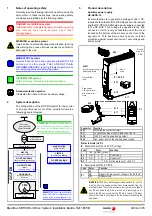
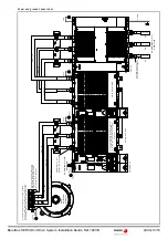
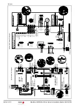
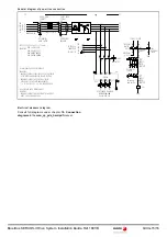
General diagram of power line connection
Electrical maneuver diagram
Consult full diagrams under chapter
10. Connection
diagrams
in the
man_qc_pds_hard.pdf
manual.
L1
L2 L3
L1' L2' L3'
L2
W
V
U
TO THE A20
CONNECTOR
QC-APSS-15
TO THE POWER TERMINALS
L1
L2
L3
L1
L3
LIM 160
PE
- S1
MECHANICAL
MAIN SWITCH
- F1
- F2
- F3
L1
L2
L3
N
- Q1
DIFFERENTIAL
BREAKER
POWER MAINS
IT A MUST TO USE FUSES
K1
EARLY OPEN
CONTACT
K2
CONTACTOR
- KM1
EARLY OPEN
CONTACT
K1
EARLY
OPEN
CONTACT
K2
GND
- S1
MECHANICAL
MAIN SWITCH
- KM1
GND
- Q1
DIFFERENTIAL
BREAKER
EARLY
OPEN
CONTACT
KA3,2
KA3,1
+24VDC
AT X35.3
RPS ENABLE
+24VDC
OFF DELAY
TIMER
-KA3
OFF DELAY
CONTACT
OFF DELAY
CONTACT
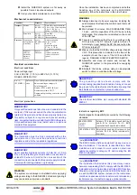
3x 400-480 VAC
FUSES F1, F2, F3: 690 V AC / 315 A min.
SIBA 20 610 32.315
SIBA 20 610 32.350
SIBA
20 189 20.315
SIBA
20 566 20.350
3x 400-480 VAC
QC-RPS-160-SN0
INPUT
OUTPUT
3x 400-480 VAC
EXAMPLES:
K1. AUXILIARY EARLY OPEN CONTACT
- AUXILIARY CONTACT GAX11 10AE OF THE GA SERIES
OF SWITCHES AND BREAKERS, LOVATO ELECTRIC.
EXAMPLES:
- AUXILIARY CONTACT HI11-P1/P3E 061813OF
APPLICABLE TO SWITCHES AND BREAKERS
P1-.../E,.../EA...,/EZ Y P3-.../E, .../EA, FROM MOELLER.
K2. AUXILIARY EARLY OPEN CONTACT
- AUXILIARY CONTACT HIV IN AUTOMATIC SWITCHES
NZM1, 2 OR 3 FROM MOELLER.
EXAMPLES:
50/60 Hz
PE
N


