Hardware configuration.
CNC 8070
5.
CENTRAL
UNIT + MONITO
R (ETX PLATFORM).
Secu
ring the U70
mod
ule
.
·60·
(R
EF
: 1911)
5.6
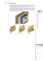
Securing the U70 module
.
5.6.1
Ambient characteristics of the cabinet.
The U70
module must be installed inside an electrical cabinet with a protection rating of
IP54 or higher. The ventilation for the electrical cabinet must be enough to dissipate the heat
generated by all the devices and components working inside. The interior temperature of
the cabinet must not exceed 55ºC (113ºF) while the unit is running.
Dissipated power.
The modules generate heat and when trying to decide whether the electrical cabinet needs
external cooling or not, one must know the power dissipated by each one of its modules.
5.6.2
Cabinet design.
When attaching the module, the following requirements must be met.
• Place the modules in a vertical position.
• To secure the module, use the holes and slots made for that purpose. Vibrations should
be avoided. If necessary use securing means made of a material which absorbs or
minimizes vibrations.
• Respect the minimum distances recommended between the enclosure walls and the
central unit to let the air flow and improve heat dissipation.
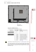
5.6.3
Ventilation.
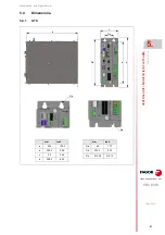
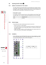
When installing the unit in the electrical cabinet, make sure to leave a clearance of at least
50 mm (1.97 inches) between it and the top, bottom and front panel of the cabinet or any
other obstacle that obstructs air flow for better heat dissipation.
CNC.
Dissipated power.
U70
85 watts.
mm
inch
A
50
1.97
A
A
A
Содержание CNC 8070
Страница 1: ...Ref 1911 8070 CNC Hardware configuration...
Страница 8: ...BLANK PAGE 8...
Страница 14: ...BLANK PAGE 14...
Страница 18: ...BLANK PAGE 18...
Страница 22: ...BLANK PAGE 22...
Страница 24: ...BLANK PAGE 24...
Страница 26: ...BLANK PAGE 26...
Страница 28: ...Hardware configuration CNC 8070 1 PREVIOUS INFORMATION 28 REF 1911...
Страница 38: ...Hardware configuration CNC 8070 2 CONFIGURATION General diagram for U60 Q7 A platform 38 REF 1911...
Страница 94: ...Hardware configuration CNC 8070 6 CENTRAL UNIT MONITOR Q7 A PLATFORM 94 REF 1911 C70 15AT...
Страница 184: ...Hardware configuration CNC 8070 8 LCD 15SVGA PASSIVE MONITOR LCD15 SVGA Overall connection 184 REF 1911...
Страница 272: ...Hardware configuration CNC 8070 18 INSTALLING A SENSOR FOR GAP CONTROL LASER MODEL 272 REF 1911...
Страница 273: ...Hardware configuration CNC 8070 273 User notes REF 1911...
Страница 274: ...Hardware configuration CNC 8070 274 User notes REF 1911...
Страница 275: ...Hardware configuration CNC 8070 275 User notes REF 1911...


