Hardware configuration.
CNC 8070
15.
EMERGENCY
BATTERY (ONLY ETX PLATFORM).
Op
eration
o
f th
e emergen
cy
b
attery.
·258·
(R
EF
: 1911)
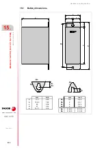
15.3
Operation of the emergency battery.
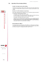
Central unit powered by the battery.
The battery only powers the central unit when a failure occurs at the power supply (a drop
of the 24 V). The Fagor battery provides an autonomy of about 20 minutes when it is fully
charged.
Response of the CNC with battery to mains failures
When a power supply failure occurs (drop at the 24 V) and there is a battery connected to
the central unit, the latter responds as follows:
• If the supply is interrupted for less than 2 seconds.
The CNC shows the corresponding warning and the system recovers fine. Errors may
occur at the CAN bus due to the lack of 24V at the remote modules.
• If the supply is interrupted for more than 2 seconds.
After the 2 seconds, the CNC shows the corresponding error and it initiates the automatic
shut-down sequence. First of all, the CNC stops any process in progress (program in
execution, tool change, etc.) and closes the CNC application. Then, the CCN shuts the
whole system down and, finally, deactivates the battery.
Recharging the battery.
The battery is charged from the central unit; DO NOT use any other device to recharge it.
The LED next to the connector blinks while the battery is being charged and it stays on when
the battery is charged. The charging process takes about 35 hours.
Содержание CNC 8070
Страница 1: ...Ref 1911 8070 CNC Hardware configuration...
Страница 8: ...BLANK PAGE 8...
Страница 14: ...BLANK PAGE 14...
Страница 18: ...BLANK PAGE 18...
Страница 22: ...BLANK PAGE 22...
Страница 24: ...BLANK PAGE 24...
Страница 26: ...BLANK PAGE 26...
Страница 28: ...Hardware configuration CNC 8070 1 PREVIOUS INFORMATION 28 REF 1911...
Страница 38: ...Hardware configuration CNC 8070 2 CONFIGURATION General diagram for U60 Q7 A platform 38 REF 1911...
Страница 94: ...Hardware configuration CNC 8070 6 CENTRAL UNIT MONITOR Q7 A PLATFORM 94 REF 1911 C70 15AT...
Страница 184: ...Hardware configuration CNC 8070 8 LCD 15SVGA PASSIVE MONITOR LCD15 SVGA Overall connection 184 REF 1911...
Страница 272: ...Hardware configuration CNC 8070 18 INSTALLING A SENSOR FOR GAP CONTROL LASER MODEL 272 REF 1911...
Страница 273: ...Hardware configuration CNC 8070 273 User notes REF 1911...
Страница 274: ...Hardware configuration CNC 8070 274 User notes REF 1911...
Страница 275: ...Hardware configuration CNC 8070 275 User notes REF 1911...

