83
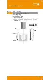
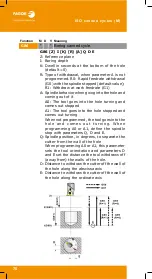
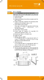
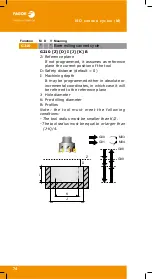
As a general rule, the structure of a cycle defining block is the
following.
It is also possible to add the definition of the canned cycle
(calling function and parameters) at the end of any block.
[G functions]
G6x
[Machining
point]
Parameters
of the cycle
[F S T D M]
G99 G1 G66 X60 Z0 I-20 F1000 S2000 M4
G99 G1 X60 Z0 F1000 S2000 M4 G68 Z2 I-2
Function
M D
V
Meaning
G66
* Pattern repeat canned cycle.
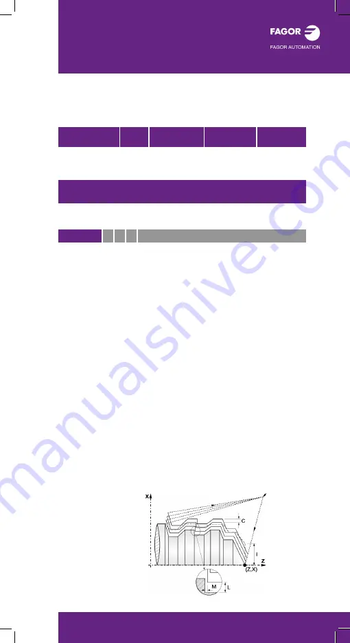
G66 X Z I C A [L] [M] [J] [H] S E P Q
X: X coordinate of the profile's starting point
Z: Z coordinate of the profile's starting point
I: Excess material (in radius)
C: Machining pass (in radius)
A: Machining main axis
A=0 main axis Z; A=1 main axis X
L: Finishing stock on the X axis (in radius)
M: Finishing stock on the Z axis (If not programmed,
it will be that indicated for parameter L)
J: Maximum travel in each section on the
machining axis
H:
Finishing feedrate
S:
Label number of the first block describing the
geometry of the profile
E:
Label number of the last block describing the
geometry of the profile
P:
Number of the subroutine where that defines
the profile
Q:
Name of the global subroutine, that contains the
definition of the profile (parameters E and S) or
of the program that contains the local subroutine
that contains the profile (parameter P)
See: Optimizing the machining operation (Page 101).
ISO CANNED
CYCLES (T)
Содержание CNC 8060
Страница 1: ...CNC 8060 65 User quick reference Ref 1906...
Страница 44: ...Work modes 44...
Страница 64: ...ISO language 64...
Страница 102: ...ISO canned cycles T 102...
Страница 128: ...Conversational cycles M 128...
Страница 136: ...Conversational cycles T 136...
Страница 150: ...Measuring and calibration cycles T 150...
Страница 169: ......

